High Accuracy Turbine Rotor Measurements Save $150,000 Per Bad Part
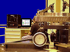
Station with operator. An operator uses Paragon to check fixturing for a precision grinder.
A new PC-based metrology system that accurately measures huge turbine components can save $150,000 for each bad part that it detects. The saving comes from avoiding additional processing. Circular geometry measurements of rotors for gas turbine generators are important because the accuracy of these components has a critical impact on bearing life. Yet, a satisfactory method has never been found to perform the required measurements, primarily because of the huge number of data points that need to be collected to determine runout, concentricity and eccentricity of the parts, which weigh up to 25,000 pounds. Turbine Metrology, Kansas City, Missouri, has developed a system that solves this problem by acquiring over 1.2 million samples per second, making it possible to perform all the necessary measurements in a single revolution. Key to the success of the new unit is an iDSC 1816 data acquisition processor (DAP) board from Microstar Laboratories, Bellevue, Washington, that simultaneously collects eight channels of sampling data without requiring any low-level attention from the PC that contains the board. This makes it possible to quickly and thoroughly evaluate the huge rotors as soon as they are machined so that rotors can be stacked up with others whose dimensions complement their own to produce smooth-running turbines.
Massive Volume of Data to Characterize Turbine Rotors
“...centering the huge rotors and rotating them while keeping them on center to a degree that won't affect the measurements is very difficult. But the hardest part has always been processing the enormous volume of data. ...When I finally had the opportunity to start addressing this problem with a clean sheet of paper I decided to take a different approach.”
Neill Fleeman, Technical Director, Turbine Metrology LLC (on the advantages of onboard processing)
Turbine rotors range up to 96 inches in diameter and 12 inches in width. During assembly, 30 of these rotors are stacked up and bolted together to form the spinning core of the power generation unit. The accuracy of these components is critical to the performance of the finished unit. If each part is only a few thousands of an inch out of flat, for example, the bearings will quickly fail and the unit will require so much downtime to repair that it may become unprofitable to operate. Using current manufacturing methods, it is virtually impossible to build these huge parts to small enough tolerances that they can be simply bolted together and deliver the required levels of performance. Instead, turbine manufacturers attempt to accurately measure each rotor and then match them up based on their flatness measurements in such as way that the entire part will run true. This creates a major measurement problem. The large size of the parts means that an enormous number of data points must be collected in order to accurately characterize them. Yet, currently high production volumes leave very little time to perform the necessary measurements.
Previous attempts at rotor measurement
Previous attempts to perform these measurements have been highly unsatisfactory. One of the biggest problems has been the mechanical setup. The rotor needs to be loaded onto a turntable that is capable of handing its enormous weight yet that possesses the accuracy to move it in a perfect circle without introducing any runout that would invalidate the measurements. The most advanced technology used up to now has been a machine with a single gauge head that is capable of taking 50 measurements per revolution. The primary problem with systems of this type is that the number of datapoints that they are capable of measuring is not enough to fully characterize the large parts. While it would be possible to collect additional points by turning the rotor through more revolutions this approach is unsatisfactory because of the difficulty of correlating signals from different revolutions to each other at the required levels of accuracy. Another problem is that lengthy setup times make it difficult to meet production volumes.
Turbine Metrology set out to solve these problems by designing a new system from the ground up. The key, according to Neill Fleeman, Technical Director of the firm, is the ability to collect far more samples in a single revolution. "I have been working this problem for nearly a decade and have seen first-hand the many unsuccessful efforts to resolve it," Fleeman said. "The mechanical aspects of centering the huge rotors and rotating them while keeping them on center to a degree that won't affect the measurements is very difficult. But the hardest part has always been processing the enormous volume of data is required to thoroughly characterize parts of these sizes. I have seen many systems that attempt to acquire and process these huge amounts data that were down more than they were operating. When I finally had the opportunity to start addressing this problem with a clean sheet of paper I decided to take a different approach."
Mechanical underpinnings
|
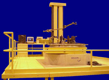
The system that Fleeman designed begins with solid mechanical underpinnings. It uses a precision rotary table from Eimeldingen Ltd. with only 0.000016 inch runout. Heidenhahn encoders are used to read the rotary position of the table. He selected four electronic lever-type gauge heads from Browne and Sharpe. These components in and of themselves are capable of accurately generating a huge amount of information in a very short period of time from a turbine rotor. The problem that Fleeman then had to face was how to handle this huge amount of information. One option was to use a dedicated data acquisition device for data collection and the PC for running the data analysis applications. This would have driven up the size and the cost of the system.
The company wanted to avoid that, but in trying to use a PC to handle both processes, they ran into another problem -- the need to find a data acquisition system that could handle the huge volumes of data required and, in the process, require as little as possible attention from the operating system of the computer on which it ran so the operating system could focus on processing the data that had already been collected. Simply finding a card that could manage the high volumes of data was difficult, but doing it independently of the operating system raised the bar by a considerable margin. "The workstation has to handle the enormous amount of data that is generated in a single rotor revolution," Fleeman said. "To move this much data around in real time, computing power has to be available when it is needed, every microsecond or so. Operating systems like Windows use up many cycles on the PC platform, and when they take control of the CPU they hold onto it for a long time in machine control terms. If data transfer functions were to run under Windows, the system would be vulnerable to a situation where Windows was occupied with other tasks, possibly interrupting the data flow."
Handling high volumes of data without involving the PC processor
The solution was the iDSC 1816 board, which combines 16-bit resolution in eight simultaneous channels of data acquisition with brick-wall anti-alias filters on each channel. The iDSC 1816 samples analog inputs at a throughput of 1.2M samples per second, with the sampling rate on each channel ranging from 8 samples to 153.6k samples per second. Onboard fourth-order analog anti-alias filters pass signals to decimation filters in the eight Sigma-Delta A/D converters. This hardware converts signals to simultaneous filtered data at 153.6k samples per second on each channel. Another unique capability offered by the iDSC 1816 is an onboard microprocessor that runs a multitasking, real-time operating system optimized for high-performance data acquisition and control applications. The intelligence on the DAP board extends the power of the Windows user interface by executing all processor-intensive routines in real time so that the software on the PC can handle more demanding applications than usual. There is never any danger of losing data regardless of how many computer cycles are dedicated to the foreground application. The data acquisition processor continues to run the special routine that collects data from the acquisition devices totally independent of the central processor.
The net result is a system that can fully characterize the turbine rotors with respect to runout, eccentricity, concentricity and flatness by collecting 720,000 measurements in a single revolution. The manufacturer of the rotors now can accurately determine their dimensions at an early stage of the manufacturing process. Rarely, the turbine manufacturer will determine that the dimensions of the piece make it impossible to use. In that case, they will save an estimated $150,000 that would have previously spent on additional machining, assembly and inspection operations. In most cases, they will find that the rotor is within specifications and, because they will have its precise dimensions, they will be able to match it with other complementary rotors in order to produce a final assembly that will run true enough to maximize bearing life. Turbine Metrology already has sold five of the highly specialized workstations to rotor and turbine manufacturers that are anxious to take advantage of these unique capabilities.
Browse other customer applications.