Simplifying Analog Input Expansion
Technical Note TN-182 Version 1.0
The signal input pins on the MSXB 001, MSXB 002, and MSXB 018 Analog Input Expansion Boards are ordered differently than the pinout of the Data Acquisition Processor™ analog connector. This can be confusing when using DAPL™ SET commands with analog input expansion.
Beginning with DAP Software version 4.3, and all DAP Software for DAPL 2000™, you can use the OPTION AINEXPAND=ON system
command to make using Analog Input Expansion Boards more intuitive. With AINEXPAND=ON, DAPL maps the pins of the Analog Input Expansion Board to match the order on the Data Acquisition Processor analog connector.
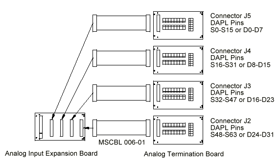
The diagram below shows the signal connections for one Analog Input Expansion Board with AINEXPAND=ON:

Each termination board is labeled S0-S15. The inputs on each termination board map sequentially to the DAPL input pins. For example, the termination board connected to J3 has termination input S0 mapping to DAPL input S32, S1 mapping to S33, S2 mapping to S34, etc. See the Analog Input Expansion Boards chapter of the dataacquisition/Accessories Manual for the pin mapping without using AINEXPAND=ON. The pin-mapping charts are especially helpful if you are making custom cabling and termination solutions.
View other Technical Notes.