
Bridge Completion Module for the MSXB 066/067
Technical Note TN-254 Version 1.0
The Vibration Measurement Problem
The Microstar Laboratories Analog Input Expansion Boards, part number MSXB 066 and MSXB 067, are 8-channel sensor interface boards for strain gauges, load cells, RTDs, and other resistive sensors. They provide a flexible interface for quarter-bridge, half-bridge, and full-bridge sensors, with or without voltage-sense feedback. Each input is connected to an 8-pin mini-DIN connector, whose pin-out is shown in Figure 1, on the MSXB 066 or MSXB 067. The cable kit MSCBL120-01K contains the mating 8-pin mini-DIN plug.

Figure 1. Pin mapping of the 8-pin input connector.
A bridge circuit requires four resistors. One, two, or four resistors are provided by the sensor and the remaining resistors are solders onto a bridge completion module MSBCM001-01. The bridge completion module is a small circuit module that plugs into the main board. One module is included is included with each MSXB 066 or MSXB 067 board. Additional modules are available from Microstar Laboratories.
Each bridge circuit has a differential voltage excitation (XF+, XF-) and a differential signal (DF+, DF-). These signals have corresponding sense signals (XS+, XS-) and (DS+, DS-)
Note: Wires connected to the sense signals are used for voltage measurements and should not carry any current.
The bridge completion module, MSBCM001-01, has locations for soldering up to four resistors for each input. It also has four jumpers for connecting the sense feedback to its associated signal, as shown in Figure 2. Figure 3 shows the schematic equivalent of one channel on the module and the connections to and from a resistive interface. Bridge completion resistors values typically are 120 Ohms, 350 Ohms, and 1K Ohms, though other values are also possible. Bridge completion resistors typically have 0.1% or 1% tolerance.
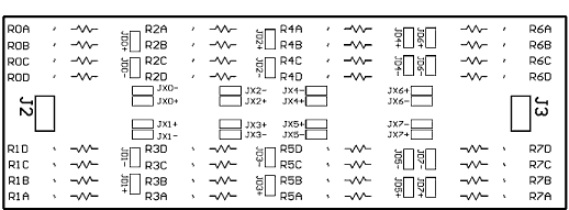
Figure 2. Layout of the bridge completion module.
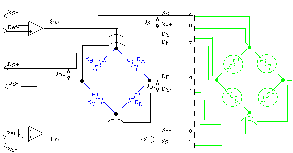
Figure 3. Schematic equivalent for one channel on the bridge completion module.
Note that the resistors are labeled RX and the jumpers are labeled JY. Any resistor or wire that needs to be soldered onto the bridge completion module is shown in blue; sensors and external wires are shown in green. The dotted line represents the interface between the input and the 8-pin DIN connector on the MSXB 066 or MSXB 067. Each channel has its own set of RA, RB, RC, and RD. The pin number of each of the eight connections is shown next to the signal name.
This technical note shows the internal and external wiring required for the most common bridge completion circuits. Because of the number of possible bridge configurations the user is responsible for wiring the inputs and soldering resistors to the bridge completion module. The Applications Engineering group at Microstar Laboratories is happy to assist with questions about configuring resistive sensors. We can also install the resistors and jumpers for you based on your input configuration.
Full-Bridge Completion
For a full-bridge configuration, no resistors need to be soldered on the bridge completion module. The two common full-bridge interfaces have 4 wires and 6 wires. The 6-wire interface has a voltage-sense feedback for the excitation voltages. Figures 4 and 5 illustrate how the 4-wire and the 6-wire interface can connect to the bridge completion module, respectively.
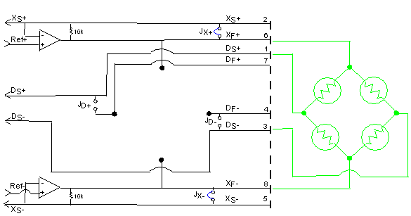
Figure 4. 4-wire full-bridge configuration. Note that jumpers JX+ and JX- need to be installed.
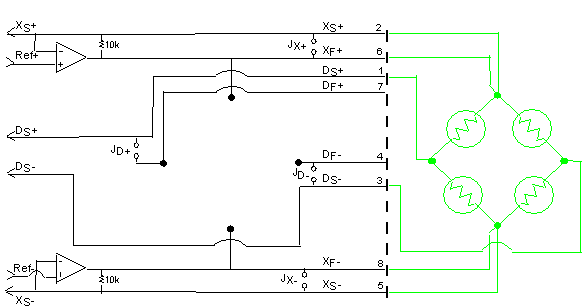
Figure 5. 6-wire full-bridge configuration with voltage-sense feedback. No jumpers need to be installed.
Half-Bridge Completion
There are ten ways to complete the bridge on the module for a half-bridge configuration, six of which are illustrated in Figures 6-11. Figures 6 and 7 show the bridge completion on the left side. The resistors can also be added to the right side of the module; the bridge completion circuit is the mirror image of what is shown in Figures 6 and 7. Similarly, the mirror image of Figures 10 and 11 is also a valid completion. In that configuration, the resistors can be added as RB and RD.
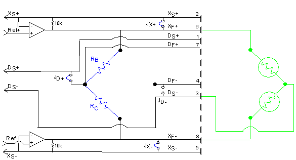
Figure 6. 3-wire half-bridge interface with bridge completion resistors on one side. JX+, JX-, and JD+ need to be installed.
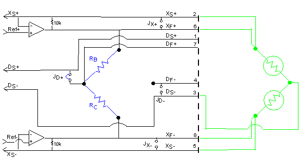
Figure 7. 5-wire half-bridge interface with voltage-sense feedback. The jumper JD+ needs to be installed.
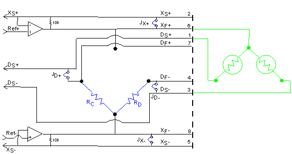
Figure 8. 3-wire half-bridge interface with completion resistors added to the bottom on the module. All jumpers need to be installed.
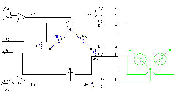
Figure 9. 3-wire half-bridge interface with completion resistors added to the top on the module. All jumpers need to be installed.
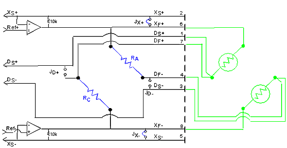
Figure 10. 6-wire half-bridge interface with completion resistors added to the opposite sides of the circuit. Jumpers JX+ and JX- need to be installed.
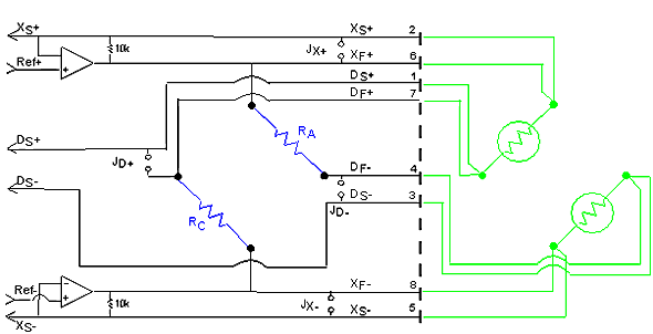
Figure 11. 8-wire half-bridge interface with completion resistors added to the opposite sides of the circuit. No jumpers need to be installed.
Quarter-Bridge Completion
A common quarter-bridge interface has 2 or 3 wires with four possible ways to connect to the bridge completion module. Figures 12 and 13 show the bridge completion of a 2-wire and a 3-wire configuration at the same position with respect to the bridge completion module. The interface is connected to the bridge completion module as RC in these diagrams; it can also be connected to the bridge completion module as RA, RB, or RD. Note that you will get inverted measurements with the sensor connected to the bridge completion module as RD.
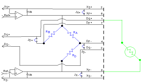
Figure 12. 2-wire quarter-bridge interface. All jumpers need to be installed.
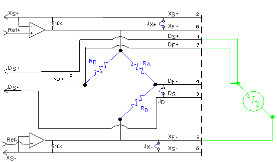
Figure 13. 3-wire quarter-bridge interface. Jumpers JX+, JX-, and JD- need to be installed.
View other Technical Notes.