Analog and Digital Filtering for Anti-Aliasing
|
|
|
|
|
|
|
Introduction

(View more DSP information.)
This note discusses well-known techniques for using analog and digital filters in combination to obtain sampled data sets free of aliasing defects. If you are already an expert on anti-aliasing techniques you will probably not find anything new here. But those who are unfamiliar with alias-avoidance techniques should find this note helpful.
About Aliasing
Additional Resources |
|---|
Suppose you want to test the audio response of a system through the frequency range from 20 to 2000 Hz. As a source of low to midrange noise to drive the test, apply your favorite Metallica album [1]. You don't care about the full audio range, so you reduce the frequency of your data sampling to 2000 samples per second, to match the frequency band that you care about. Then capture measurements of system response and perform an unhurried FFT analysis. The most important reason for not performing your experiments this way: your results will be invalid. The configuration just described disregards the Nyquist band limit and is subject to severe aliasing problems.
The choice of Metallica as a test signal is not bad. Though heavy in the bass, the biting edge of the distortion produces plenty of harmonics to cover a wide audio range. So there is no lack of spectral information. Rather, it will be the overabundance of it, far beyond the range of interest, that will lead to problems.
The digitizer circuits of a Data Acquisition Processor board will track extreme high frequencies, through the audio range and far beyond. For all practical purposes, when it is time to collect a sample, that sample evaluation is instantaneous. Now suppose the Data Acquisition Processor is tracking a very high frequency waveform, up and down. Every time it passes the top of the fast waveform, the sampling captures another value. What will the results look like in the data set?
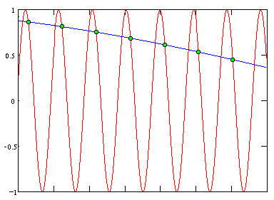
The data will be indistinguishable from measurements of a very low frequency signal. This sampled representation of a signal that looks like a signal at a completely different frequency is the phenomenon known as aliasing.
"After sampling a continuous signal, frequencies above and below the Nyquist frequency (1/2 of the sampling frequency) cannot be distinguished. This is a fundamental limitation of sampled data systems. A signal to be sampled might have frequency components higher than the Nyquist frequency. If so, the effects of these high frequencies on discrete measurements are difficult or impossible to predict, adding or subtracting depending on signal phases.
"Frequencies in bands centered at all multiples of the sampling frequency can corrupt measurements in the low-frequency band. The only way to guarantee good data is to make sure that problem-causing high frequencies are not present in the analog signal when it is sampled." [2]
Frequency bands that can cause aliasing problems
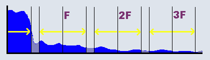
Applications sometimes take unnecessary risks by assuming that all out-of-band signals are "random," that is, zero mean and statistically independent. If these assumptions are true, yes, error will tend to cancel over time and the averages will go toward a small flat "noise floor" that can be disregarded. But if the interfering noise is consistent, especially if there is any kind of cause-and-effect relationship, you have no such guarantees. Instead of averaging to zero, the effects can converge toward a persistent offset, leaving you no way to know that this bias was not really present in your signals.
Avoid Aliasing Damage by Oversampling
First and most fundamentally, pick a sampling frequency at least twice the highest frequency in the band to be measured. That keeps all the desired frequencies below the Nyquist limit. For the case of a 2000 Hz band, the sampling frequency can be no lower than 4000 samples per second.
But when operating at the theoretical limit, any frequency outside of the band of interest has the potential of introducing aliasing artifacts into your data set. To reduce the number of bands that might possibly interfere with your captured signal band, and to keep these as far away as possible from the desired band, you can make your sampling frequency higher than the minimum theoretical limit. This is known as "oversampling."
Higher sampling frequency separates problem bands
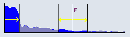
For the case of the 2000 Hz band, if the sampling is increased from 4000 to 8000 samples per second, frequencies in the range 2000 Hz to 6000 Hz can be distinguished from those in the 0 to 2000 Hz band and can no longer cause damage. Frequencies above 6000 Hz remain as potential problems. For accurate sampling, filtering should remove those high frequencies before sampling.
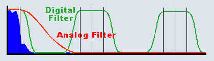
Analog filtering avoids high-frequency aliasing
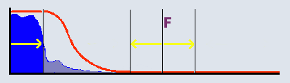
You will find that the design of an analog filter to preserve the desired 2000 Hz band accurately, while completely attenuating a frequency band less than two octaves above that, is actually quite a challenge. The higher the sampling frequency, and the more the problem bands are separated, the easier the filter design problem becomes.
That is the basis of the oversampling strategy. Sample at a higher rate than you need for the final result, using a simple analog filter to avoid any exposure to aliasing from extreme high frequencies. That leaves you with a valid sampled data set, but covering a wider frequency band than what you need. This is only part of what you want to accomplish, but at least it is achieved easily. For multi-channel applications, the MSXB 048 filtering termination boards from Microstar Laboratories provide the analog filtering for 16 channels. Differential signals from bridged sensor configurations can use MSXB 067 bridge interface boards for their filtering.
Returning to the audio measurement application, suppose that the sampling is done at 40000 samples per second rather than the theoretical minimum of 4000 samples per second. (A Data Acquisition Processor will have no trouble with this, unless you need to process 20 channels at this rate simultaneously. Then be careful!) A simple second-order biquad filter is sufficient for the analog filtering. After that, you will know:
- the frequencies in the range of 38000 to 42000 and higher are completely eliminated, so they do not corrupt the data set,
- the frequencies in the range of 0 to 2000 are represented exactly,
- other frequencies are possibly attenuated, possibly aliased, but they do no harm to the 0 to 2000 Hz band of interest.
Removing Unneeded Frequencies
The data set sampled at the high frequency uses most of the samples for distinguishing frequencies that you don't care about. If you remove those unimportant frequencies from your data set using digital filtering, you can discard redundant samples safely. The design of the digital filters turns out to be relatively easy — it is a built-in feature of the DAPstudio software package, for example.
We know from earlier discussions that 8000 samples per second sampling can represent the desired frequency band accurately, so the sample rate can be reduced from 40000 samples per second to 8000 samples per second without losing any information in the desired frequency band. That would be decimation by a factor of 5.
Before making this reduction, it is necessary to ensure that this resampling will not introduce new aliasing problems. At the desired 8000 samples per second sampling rate, as previously discussed, all frequencies that could cause aliasing problems are above 6000 Hz. Apply a digital filter that preserves the frequency band from 0 to 2000 Hz, eliminates frequencies from 6000 Hz upward, and makes an arbitrary smooth transition between.
After combined filtering, decimation is safe
Between the easy analog and easy digital filtering, the combination completely removes any frequency band that could cause aliasing problems at the lower sampling frequency. After that, you can safely decimate the data set: in the example, repeatedly take one sample and discard the next four. Frequencies from 4000 to 6000 Hz that survive the digital lowpass filter will alias onto the frequencies from 2000 to 4000 Hz — and you don't care. No information is lost in the important 0 to 2000 Hz band.
The FIRLOWPASS command provided by the
DAPL operating system can be used to perform both the
lowpass filtering and decimation in one operation.
FIRLOWPASS(IPIPE0, 5, DECIMATED)
This is very aggressive filtering, arguably more rigorous than you need, but it is accurate, extremely simple to use, and a good fit for this particular application.
We can observe briefly that the complete solution, with analog front-end filters and distortion-free "brick- wall" anti-aliasing filters provided on the Microstar Laboratories iDSC Data Acquisition Processor boards, covers all of the analog filtering, digital filtering, and decimation steps automatically, on multiple channels that are completely configurable, and you do not need to be a filter design specialist.
Conclusions
As far as the end results go, it doesn't make any difference how the high frequencies that can lead to aliasing corruptions are removed, just as long as they are not present in the signal during sampling. It is difficult to design an analog filter to precisely isolate a desired frequency band without distortion, but easy to design a simple analog filter to reject extreme high frequencies before sampling at a high rate. Then it is easy to design digital filters (or apply pre-designed filters) to band- limit the digitized signal, and then decimate to the desired final sample rate without losing desired information.
In the example of this note, the frequencies and channel count were low, so the oversampling and filtering techniques led to a very simple solution. The same principles apply in more sophisticated, high-performance systems with higher frequencies, more channels and more stringent frequency selectivity requirements. A perfect example is the iDSC family of Data Acquisition Processor boards, using precision higher-order analog filters, high- speed tracking converters, and multiple stages of configurable digital filters to obtain high selectivity and alias-free sample values at sampling rates exceeding 100000 samples per second.
Footnotes and References:
Return to the DSP page.