Click on the image to see the full-size animation.
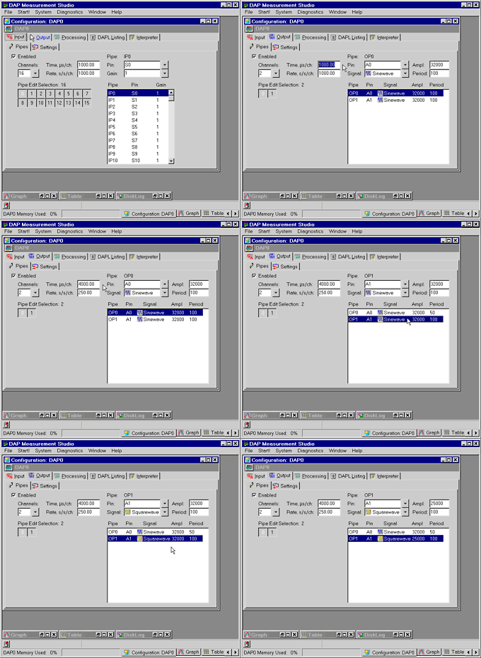
A DAP board can generate periodic output data. This application configures a DAP board to generate two waveforms and send data to its analog outputs DAC0 and DAC1. The application performs the following operations.
The Time edit box specifies how often to update the output pin. This application updates the output pin every 4000 microseconds, which is 250 updates per second per channel.
The Pin combo box specifies A0 and A1 for output on analog output pins 0 and 1, which are DAC0 and DAC1 on an MSTB009-09-A2C-B.
The Signal edit box specifies a Sinewave output and a Squarewave output.
The Ampl edit box specifies the amplitude of the waveforms.
The Period edit box specifies the period of the waveforms.
The DAP samples values from an ideal Sinewave with an amplitude of 32000 and a period of 50 samples and sends the values to A0. Because of sampling effects, the output values range from approximately -32000 to approximately +32000. The result is a 5Hz sine wave, because the output A0 updates 250 data values per second per channel.
The DAP also samples values from an ideal Squarewave with an amplitude of 25000 and a period of 100 samples and sends the values to A1. Because of sampling effects, the output values range from approximately -25000 to approximately +25000. The result is a 2.5Hz square wave, because the output A1 updates 250 data values per second per channel.
File|New.Output|Pipes tab and check the Enabled checkbox.4000" in the Time edit box and "50" in the Period edit box.OP1 to highlight it in the edit box on the right-hand side.Squarewave from the Signal combo box.25000" in the Ampl edit box.Start! or press Alt-S on the keyboard.