Q10027 Active or passive 4-20 mA loops
Signals from my sensors are driven over a large distance by 4-20 mA current loop transmitter modules. These modules come in two varieties, "active" or "passive." Which one should I use, and how do I connect it?
Though it is common, the terminology of active and passive for 4-20 mA signal transmitters is very misleading. The devices are always active. The distinction is really in the physical location of the ground reference point and the power source. Which configuration you should use depends on the physical constraints and the kind of transmitter devices you use. Both configurations are compatible with DAP systems.
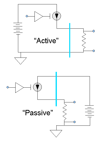
If you trace the current path through the two circuits, you will see that the two current loops are identical. The connections from the load resistor to the termination pins are also identical.
The active configuration provides excitation power at the sensor/transmitter end of the signal path. Low level sensors such as microphones or bridged load cells need a clean power source close to the sensor, and this source typically serves as the power source for the transmitter too. We recommend trying this configuration first, if your equipment supports it. The single ground reference point is typically the ground point of the transmitter amplifier. To avoid ground loops and signal noise, a "floating" termination at the receiver end is best, with the voltage across the load resistor sensed by a differential input.
The passive configuration can be used with any transmitter that does not incorporate the power supply within the transmitter module itself. This configuration has an advantage in situations where physical constraints make it difficult to locate a power source near the transmitter, or when it is more economical to use a centralized power supply for a large number of signal lines. While the power supply and ground reference are physically located at the DAP termination end, the DAP or accessory boards cannot supply enough current and are not connected to the power circuit directly. You will need to provide your own power supply for this purpose.
One subtle difference to watch for: though the transmitter output line is the same for both configurations, in the active configuration the second line of the loop operates near ground potential, and in the passive configuration it operates near the power supply level. This affects how you will wire your connector panels.
L23955