Q10065 Layout of expansion board prototyping area
I need to have my electronics shop mount termination components for a lot of signal lines. How is the MSXB037 expansion board laid out?
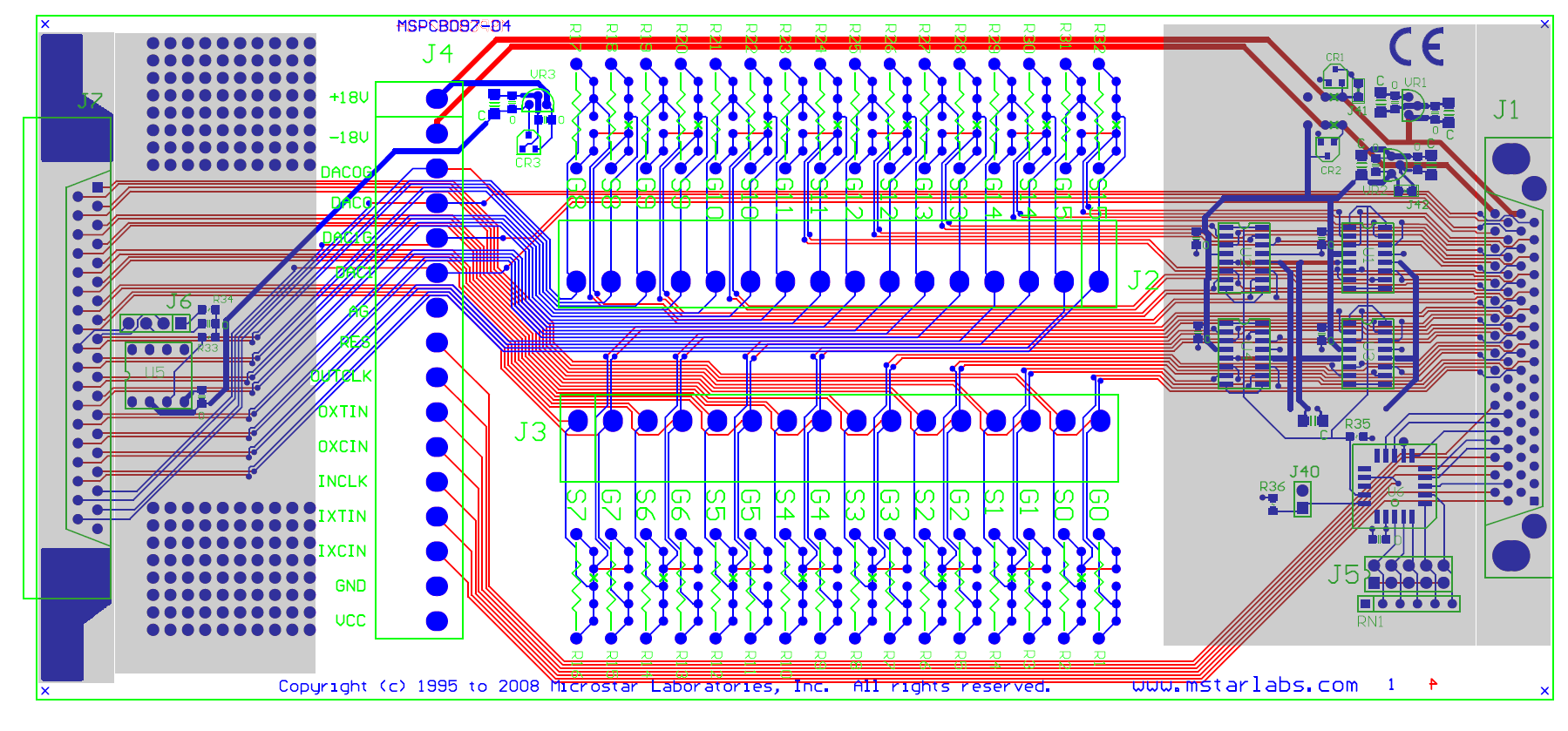
The MSXB037 analog expansion board is laid out as illustrated in a
separate image file (about
111K). The prototyping area reserved for termination components
is the large area with brighter background at board center. The connectors
and their labels are indicated in green. Visible traces appear blue. Hidden
traces, buried or on the back side, appear red. Locations where termination
resistors would typically be mounted are indicated in green. Locations where
surface traces are sometimes cut are indicated by green X marks.
There are some uncommitted prototyping pads at the far left corners.
General information about mounting termination components on termination boards is given in the knowledge base article Q10028 - Mounting termination resistors on boards. Though that article specifically discusses simple termination boards, the information also applies to MSXB037 analog expansion boards.
L24076
Also see article Q10028