Q10113 Configuring master-slave applications with DAPstudio
How do I configure DAPstudio to run an application with multiple boards in a master-slave configuration?
Configuring an application with multiple DAP boards is a lot like configuring every DAP board independently. At least from the viewpoint of DAPstudio, the DAP boards do seem to operate independently. Each board involved in the application must be given its own separate configuration, with its own communication channels to transfer the data to the host system.
There are many possible variations. This particular example is for two DAP 5400a boards that capture 8 channels each at a high sustained rate, with all sampling synchronized. One DAP 5400a board could capture the 16 channels, but it could not do so simultaneously, and the application requires rigorous simultaneous hardware clocking. (Not very many applications really need this, but some do.) Other kinds of application configurations might involve:
- Different number of DAP boards.
- Models of DAP boards that use ungrouped multiplexed sampling on each board.
- Complex configurations of I/O channels.
- Faster or slower sampling rates.
- Data capture initiated with hardware or software triggering.
Here are the steps to configure the example application.
Make sure that you have the appropriate DAPtools software installed and operating on your system. For most systems, this will mean using the current DAPtools software version.
It will make a difference which DAP board is the master and which is the slave -- if for no other reason, than you must distinguish which signals are wired to which board. The Windows system will provide board names
DAP0andDAP1, and it will do this in a consistent and completely repeatable manner. But you can't know what the Windows system will do when it sees the DAP boards for the first time.Here is one way to force the boards to be assigned Windows names in a predictable way. Note the serial number of the first DAP board, from the sticker on the back of the board. Install this board in the desired host slot. Boot up the system and verify in the Control Panel application for Data Acquisition Processors that the DAP board is recognized. It will have the assigned name
DAP0. For the example, this board will be configured as the slave board.Now, power down your system. Install the second DAP board in another slot, and again power up the system. Verify that this board is also recognized properly, verifying the serial number. The first board will retain its identity as
DAP0and the second board will be assigned the nameDAP1. Repeat these steps for each board. For the example, there are two boards, soDAP1is the last board and it will serve as the master.Now power down your system. Unseat the DAP boards one at a time and attach the master-slave daisy-chain cable, board to board. Now reseat the boards in their bus connectors carefully. Your system is now ready to run. On next boot, all of the boards will have the intended identities.
Make sure you have your DAPstudio software installed and working correctly. Run DAPstudio.
Open the
Configurationwindow and click on it to select. Next, go to the main menu line and select
System | Board Detect and Update
to verify that DAPstudio is aware of the current board configuration. Return to the main menu and select
System | Multiple Boards Configure.
This will add a pane on the left side where you can navigate and click on the DAP board icon for the board you wish to configure. If you don't see all of the boards in your system, click theAdd DAPnear the upper left of the configuration window. For this example, bothDAP0andDAP1should be available.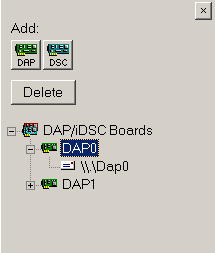
Enabling multiple boardsAt the left pane in the
Configurationwindow, click to selectDAP0, and then click theInputtab. In the right-side pane, verify that theEnabledbox is checked. Configure the number of channels and timing as you would in an ordinary single-board application. For the example application, the DAP boards are model DAP5400a, and only one channel group of 8 channels isSPG0is necessary. Select a time interval of 4 microseconds per channel. (4 microsecond intervals per sample on 8 channels produces 2 million samples per second.)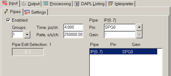
Configuring channels and ratesRepeat these steps, selecting
DAP1this time. Apply all of the same channel configurations. Typically, master-slave applications will have identical configurations of this sort because master-slave activity is coordinated at the hardware level. If the hardware is used differently in the two configurations, that will most likely lead to some kind of invalid result (or worse).Still in the
Configurationwindow, click to selectDAP0in the left pane, and then click theSettingssub-tab. Typically, keep all of the default option settings except for the Synchronization option. Select theSlaveoption forDAP0.Do the same thing again, this time selecting
DAP1in the left side pane, and selecting theMasteroption forDAP1.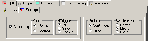
Configuring the master/slave mode for the master boardStill in the
Configurationwindow, click to selectDAP0in the left pane, and then click theProcessingtab and theSend to PCsub-tab. Select all of the signal channels that you want sent to the host through the $BinOut communication pipe fromDAP0. For the example application, there is one channel group with 8 channels and we want data from all 8 channels, so make sure that all of the signal channels for this DAP are checked.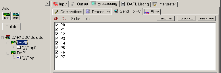
Selecting channels to transfer from a DAP board to the hostClick to select
DAP1in the left pane, and then click theProcessingtab and theSend to PCsub-tab. Select all signal channels forDAP1in a manner similar toDAP0.Your host will not be able to interactively process all of the 4 million samples per second, so you will need to route the data to log files. If a disk log window is already defined, you can reconfigure it, otherwise, use the main
Window | New Disk Logmenu to create a new disk log window. Click on that window, and then click on theChannels...item that appears in the main application menu. You will see all of the channels that you previously set up for data transfers to the host. You can only log data to a file from one source, so select all of theDAP0channels, then click OK.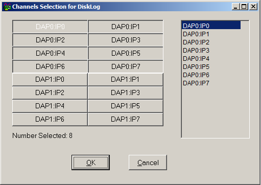
Selecting data channels to logBack in the Disk Log window, click on the button marked "
..." near the right hand side. Navigate to the folder you want to use on your disk drive, and then specify the name of the log file to receive the data. The file name should provide an indication that the data came fromDAP0.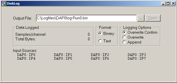
Log file setup for one of the DAP boards
Now create a second disk log window using the main
Window | New Disk Logmenu. Follow all of the same steps, but this time when you use theChannels...dialog, select the channels that transfer fromDAP1. The file name should provide an indication that the data came fromDAP1.
Log file setup for the other DAP boardVerify that your configuration works. Click on the
Processingtab and theInterpretersubtab. Click theStart!main menu item. Click on the icon forDAP0and forDAP1in the left side panel. The display will show the commands that went to each board.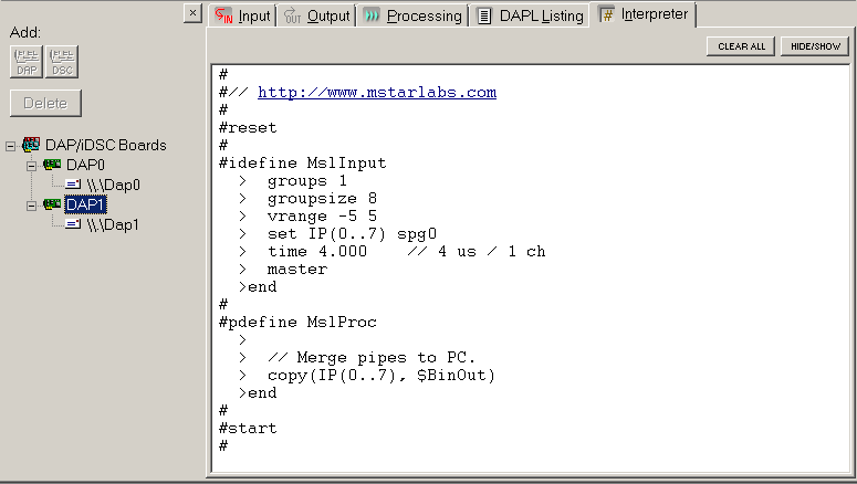
Observing configuration commands sent to each DAP board
DAPstudio knows how to start the master and slave boards. The slave board, for this example
DAP0, is started first because it must be running and ready at the time the master board hardware begins sending hardware control signals. Click theStop!main menu item to complete the test run. Check your system disk drive to verify that the files were written properly.
L24766