MSXB 023 Quadrature Decoder Board
Technical Note TN-171 Version 1.1
This Technical Note includes information about products that are now Obsolescent.
The Microstar Laboratories Quadrature Decoder Board, part number MSXB 023-01, allows a Data Acquisition Processor to read quadrature-encoded signals through the digital port. Quadrature encoded signals are often used to measure the angular (rotational) velocity and angular position of wheels, gears, and motors.
A quadrature encoded signal consists of a pair of square waves that are 90 degrees out of phase with each other. The speed of rotation determines the frequency of the square waves while the direction of rotation determines the phase of the square waves. The Quadrature Decoder Board decodes quadrature encoded signals and keeps track of the angular position by means of an up/down counter.
The Quadrature Decoder Board has four input channels. Each channel can measure quadrature encoded signals with frequencies up to 1 Mhz and has a counter resolution of 16 bits. The counter resolution can be extended to 32 bits via software. Up to 6 Quadrature Decoder Boards can be used in a system for a total of 24 channels.
The Quadrature Decoder Board can be used in conjunction with a Digital Expansion Board to provide digital input and output expansion as well as quadrature inputs. When used in conjunction with digital input expansion, up to 3 Quadrature Decoder Boards can be used for a total of 12 quadrature channels and one Digital Expansion Board can be used for a total of 64 digital inputs.
Hardware Configuration
The Quadrature Decoder Board connects to the DAP with a 100 line ribbon cable, part number MSCBL 036-01. This cable connects connector J1 of the Quadrature Decoder Board to the Digital Input/Output Port of the DAP.
Note: Never connect or disconnect the Quadrature Decoder Board while the DAP is powered.
The Quadrature Decoder Board provides four independent input channels. Each input channel consists of two terminals for quadrature encoded signals and two terminals for their corresponding grounds. Connector J5 provides termination for four input channels.
The input channels are Schmitt-triggered CMOS. The positive-going threshold for a "1" input is 4.0V. The negative-going threshold for a "0" input is 1.0V. The inputs have 4.7K pull-up resistors that allow TTL-compatible signals to be applied to the inputs. If TTL-compatible signals are applied, the TTL driver must allow its output to be pulled up above 4V. The inputs sink no more than 10 microamps for a "1" input and source no more than 1.1 milliamps for a "0" input.
Note: If a voltage greater than 5V or less than 0V is applied to an input, damage to the Quadrature Decoder Board may occur. Signals must not be applied to the Quadrature Decoder Board while the DAP is off or damage to the Quadrature Decoder Board may occur.
A quadrature encoded input consists of two square wave signals that are 90 degrees out of phase with each other. These two signals make up four states, where each state is defined as the period in which both signals are constant. The minimum period of each state is 200 nanoseconds. The minimum low period of each signal is 400 nanoseconds. The minimum high period of each signal is 400 nanoseconds. The minimum period of each signal is 1000 nanoseconds, which corresponds to a maximum frequency of 1 Megahertz.
As seen from the DAP, the Quadrature Decoder Board consists of two input ports: a control port and a data port. Reading the control port freezes the values of all the counters on the Quadrature Decoder Board. Reading the data port reads one of the four counter channels in ascending order.
At the start of an application, the control port must be read first. After reading the control port, reading the data port would read the first channel counter value. Reading the data port again would read the second channel counter value. Subsequent reads from the data port would read ascending counter channels up through the fourth channel. Reading the control port again would freeze new count values in all channels. Reading the data port again would read the new counter value from the first channel as the cycle continues. Note that because the channels have to be read in order, skipping channels is not allowed. However, not all 4 channels on each board have to be read. For example, the first two channels can be read while omitting the third and fourth channels.
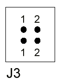
All counters on the Quadrature Decoder Board are reset when the DAP is reset. The counters can also be reset manually by removing the pin 2 jumper on header J3. Replacing the pin 2 jumper on header J3 allows the Quadrature Decoder Board to resume normal operation. The pin numbering on header J3 is:

More Than One Quadrature Decoder Board
If more than one Quadrature Decoder Board is used in a system, a custom daisy-chain cable must be used so that the J1 connectors of all Quadrature Decoder Boards are connected together in a daisy-chain. If more than three Quadrature Decoder Boards are to be connected to a DAP, an external power supply is required. Each Quadrature Decoder Board draws about 0.6 Amps at 5 volts. The MSXB 023-02 model is available with the DAP power disconnected and with a connector for external power.
Note: It is best to power the MSXB 023-02 from the host PC's power supply so that both the MSXB 023-02 and the DAP are powered on and off at the same time. If this is not practical, then external power to the MSXB 023-02 must be applied before powering on the DAP and must be disconnected after powering off the DAP.
Input Range
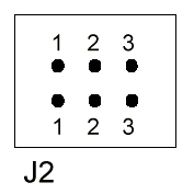
There are three address jumpers on the Quadrature Decoder Board that allow multiple Quadrature Decoder Boards to be used with one DAP. The address jumpers are located on jumper header J2. The pin numbering of header J2 is:

The board address determines the address of both the control port and the data port. The board address is selected by installing jumpers on header J2 as shown in the table below:
Hardware Board Address   Jumpers   Software Control Port  Software Data Port
         0              1, 2, 3           B3                     B0
         1              1, 2              B3                     B1
         2              1,    3           B3                     B2
         3              1              Not valid              Not valid
         4                 2, 3           B7                     B4
         5                 2              B7                     B5
         6                    3           B7                     B6
         7              None           Not valid              Not valid
|
The control port address can be shared by up to three Quadrature Decoder Boards. The control port has two hardware selectable addresses: B3 and B7. The data port address ranges from B0 through B7, excluding B3 and B7. When using multiple Quadrature Decoder Boards, each board must have a unique data port address.
Software Configuration
The Quadrature Decoder Board is controlled through DAPL in a similar manner to the way the Counter Timer Board is controlled. The input channel list consists of reading the control port to freeze all counter values and then reading each individual counter value from the data port. The minimum sampling period is 1 microsecond. With the board address set to 0, the following DAPL program listing reads four channels from a single Quadrature Decoder Board:
   IDEF QuadIn 5
      SET 0 B3 ; Control port - freezes all counter values
      SET 1 B0 ; Read channel 0 counter value
      SET 2 B0 ; Read channel 1 counter value
      SET 3 B0 ; Read channel 2 counter value
      SET 4 B0 ; Read channel 3 counter value
      TIME 10
   END
In the next example, two Quadrature Decoder Boards are used. The first board address is set to 0 and the second board address is set to 1. Note that only two channels on the second board are used. These two channels are channel 0 and channel 1 because the channels are read in ascending order.
   IDEF QuadIn 7
      SET 0 B3 ; Control port - freezes counters on both boards
      SET 1 B0 ; Read channel 0 counter value on first board
      SET 2 B0 ; Read channel 1 counter value on first board
      SET 3 B0 ; Read channel 2 counter value on first board
      SET 4 B0 ; Read channel 3 counter value on first board
      SET 5 B1 ; Read channel 0 counter value on second board
      SET 6 B1 ; Read channel 1 counter value on second board
      TIME 10
   END
Processing Counter Data
Two DAPL commands provide processing specific to the counter data:
   QDCOUNT ( <in_pipe>, <pipe1> [,<start_value>])
   CTRATE ( <in_pipe>, <pipe2> )
QDCOUNT maintains an internal 32-bit representation of the current counter value. If <pipe1> is a long pipe, the 32-bit count is written to <pipe1> each time a counter value is processed. If <pipe1> is a word pipe, the least significant word of the 32-bit count is written to <pipe1> each time a counter value is processed.
The optional <start_value> parameter specifies the starting value of the 32-bit internal count. If this parameter is omitted, the starting value of the internal count will be the first value read from the <in_pipe>. The optional parameter can be either a variable or a constant.
The Quadrature Decoder Board must be sampled fast enough to handle wrap around. A channel must be read before its counter increments or decrements by 32767. QDCOUNT determines the direction of wrap around by determining which direction has the smallest difference between the present count value and the previous count value. For example, if the previous count value read from the Quadrature Decoder Board was 32767 and the current count read is 0, then the wrap around was in the reverse direction because decrementing from 32767 to 0 involves 32767 steps while incrementing from 32767 to 0 involves 32769 steps, which would violate the assumption that the board is being sampled fast enough.
The following listing keeps track of the positions of three quadrature input signals:
   RESET
   PIPES P0, P1, P2
   IDEF QuadIn 4
      SET 0 B3 ; Control port - freezes all counter values
      SET 1 B0 ; Read channel 0 counter value
      SET 2 B0 ; Read channel 1 counter value
      SET 3 B0 ; Read channel 2 counter value
      TIME 10
   END
   PDEF QuadCount
      QDCOUNT ( IPIPE1, P0) ; Keep track of channel 0
      QDCOUNT ( IPIPE2, P1 ) ; Keep track of channel 0
      QDCOUNT ( IPIPE3, P2) ; Keep track of channel 0
      FORMAT ( P0, P1, P2) ; Output positions
   END
   START QuadIn, QuadCount
CTRATE computes the differences between adjacent count values read from an input channel. The differences are proportional to the average frequency of the input signal. CTRATE is an internal DAPL command that is also used with the Counter Timer Board.
View other Technical Notes.