MSXB036: Counter/Timer Board
Technical Note TN-190 Version 1.2
The Microstar Laboratories Counter/Timer Board, part number MSXB 036, provides high-speed counting and timing functions to a Data Acquisition Processor. The Counter/Timer Board has 10 high-speed counters, each of which has 16-bits of resolution. Eight of the counters have maximum input frequencies of 6.8 MHz, while two have prescalers that allow input frequencies up to 100 MHz. The Counter/Timer Board includes a digital expansion port.
Hardware Configuration
The Counter/Timer Board may be connected to a Data Acquisition Processor with a 100-line cable adapter board, part number MSCBL 046-01 and a 100-line cable, part number MSCBL 054-01 or part number MSCBL 056-01. The MSCBL 046-01 attaches to the Digital Input/Output Port of the Data Acquisition Processor. The MSCBL 054-01 or MSCBL 056-01 connects the cable adapter board to connector J1 of the Counter/Timer Board. The Counter/Timer Board may also be connected directly to the Digital Input/Output Port of the Data Acquisition Processor with a 100-line adapter ribbon cable, part number MSCBL 058-01.
Warning: Never connect or disconnect the Counter/Timer Board while the Data Acquisition Processor is powered.
The Counter/Timer Board provides ten independent counter inputs. TTL input signals may be applied between a counter input pin and ground on connector J3 of the Counter/Timer Board. Connections should be made only to pins labeled CTC_SOURCE_ and ground pins. The counter inputs are rising-edge triggered and the prescaler inputs are falling-edge triggered.
The Counter/Timer Board has two socketed termination resistor networks, RN9 and RN10, adjacent to J1. The resistors are installed in the sockets when the boards are shipped from the factory. For single-board systems the resistors should remain installed. For multiple-board systems, only one board may have the resistors installed. The board farthest from the Data Acquisition Processor should have the resistors installed in it. If more than one board in a system has the resistors installed, the system may fail.
The Counter/Timer Board reserves digital input ports zero and one and reserves digital output ports zero through seven. Other digital expansion boards must be configured for other port addresses when used with a Counter/Timer Board.
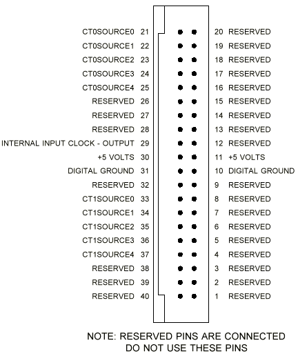
Connector J3 is a 40-line cable connector for counter inputs. The pin numbering of connector J3 is:

Figure 1. Counter Input Connector
Warning: If a voltage greater than 5 V or less than 0 V is applied to an input, damage to the Counter/Timer Board may occur. Signals must not be applied to the Counter/Timer Board when power to the Counter/Timer Board is off or damage to the Counter/Timer Board may occur.
The minimum low period of a counter/timer input signal is 70 nanoseconds and the minimum high period is 70 nanoseconds. The maximum frequency for an input signal is 6.8 MHz.
Counter inputs 0 and 1 are connected to prescalers. Each prescaler is a circuit that divides its input frequency by 1, 2, 4, 8, or 16. The divisor is selected by means of a jumper. Header J5 selects the divisor for input 0 and J6 selects the divisor for input 1. The diagram below shows the jumper positions for the various divisors. The diagram is oriented such that pin 1 is closest to the bottom edge of the circuit board.

Figure 2. Counter Input Prescalers
For input frequencies less than 6.8 MHz, the jumper should be in position 5 to select a divisor of 1. The right-most column in the figure above shows the appropriate frequency ranges for the various divisors. It is advisable to use the lowest divisor possible to maximize count resolution.
Connectors J7 and J8 are high frequency SMB-type coaxial connectors for input pins 0 and 1. Either connector J3 or these connectors can be connected to inputs with no change to the configuration of the Counter/Timer Board. Connector J7 connects to counter input 0 and J8 connects to counter input 1. J7 and J8 should be used for input frequencies greater than 20 MHz.
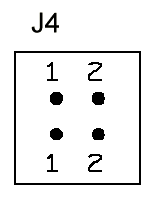
Header J4 is for future expansion. Pin pairs 1 and 2 should have jumpers installed.

Digital Input/Output
Connector J2 provides 16 bits of digital input and output. The pinout of this connector is the same as the pinout of the Data Acquisition Processor digital input/output connector. The digital input port is accessed as port 0 and the digital output port is accessed as port 4. To use the Counter/Timer Board, the DAPL command OUTPORT is required. The output port type of the Counter/Timer Board is zero.
The following example illustrates digital I/O:
   OUTPORT 0..7 TYPE=0

   RESET
   PIPES P0
   IDEF A 1
      SET IPIPE0 B0
      TIME 10000
      END
   PDEF B
      PRINT
      DIGITALOUT(P0, 4)
      END
   START A,B
Software Configuration
The DAPL SET command is used to access a counter input. Counter commands are:
   SET IPIPEx CTLy
   SET IPIPEx CTz
A CTLy input (Counter Timer Load) freezes the values of all counters in counter circuit "y". Counter circuit 0 contains input counters 0 through 4 and counter circuit 1 contains input counters 5 through 9. Counting continues after the count values are frozen.
A CTz input (Counter Timer read) reads the value of a specified input counter. The value of "z" ranges from 0 to 9.
The following example illustrates an input procedure which reads four counter inputs:
   IDEF A 5
      SET IPIPE0 CTL0
      SET IPIPE1 CT0
      SET IPIPE2 CT1
      SET IPIPE3 CT2
      SET IPIPE4 CT3
      .
      .
      END
If a counter read command is followed by the code 10, the selected counter ignores the state of its hardware input pin and instead counts an internal 5 MHz clock. For example:
SET IPIPE3 CT2 10
Processing Counter/Timer Data
Two DAPL commands provide processing specific to counter/timer data:
   CTCOUNT (<in_pipe>, <pipe1>)
   CTRATE (<in_pipe>, <pipe2>)
CTCOUNT maintains an internal 32-bit representation of the current counter value. If <pipe1> is a long pipe, the 32-bit count is written to <pipe1> each time a counter value is processed. If <pipe1> is a word pipe, the least significant word of the 32-bit count is written to <pipe1> each time a counter value is processed.
CTRATE computes the differences between adjacent values read from an input counter. The differences are proportional to the average frequency of the input signal. The frequency values are written to <pipe2>.
The following listing illustrates a complete two input frequency counting application:
   OUTPORT 0..7 TYPE=0
   RESET
   PIPES P1,P2
   IDEF A 3
      SET IPIPE0 CTL0
      SET IPIPE1 CT0
      SET IPIPE2 CT1
      TIME 1000
      END
   PDEF B
      CTRATE (IPIPE1, P1)
      CTRATE (IPIPE2, P2)
      FORMAT (P1, P2)
      END
   START A,B
External Power
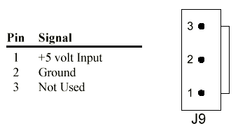
The Counter/Timer Board allows an external 5-volt power supply to be connected through connector J9. Connector J9 is a male Molex connector part number 26-60-4030 and mates with Molex connector part number 09-50-3031. The Counter/Timer Board typically requires 1.2 Amp at +5 Volts DC.

Figure 3. External Power Connector
When an external +5 Volt power supply is connected to the board all shunts on jumper header J11 must be removed. Jumper header J11 is located near J1. on the top left corner of the board. Removing all the shunts from J11 disconnects the Data Acquisition Processor's +5V power supply from the board's +5V power supply.
Note: It is best to power the Counter/Timer Board from the host PC's power supply so that both the Counter/Timer Board and the DAP are powered on and off at the same time. If this is not practical, then external power to the Counter/Timer Board should be applied before powering on the DAP and should be disconnected after powering off the DAP.
Warning: When using an external power supply all shunts on J11 must be removed. Otherwise the external power supply or the host PC power supply could be damaged.
External Enclosure Option
The MSXB 036 Counter/Timer Board is available with a single-board external enclosure option. The external enclosure provides shielding and is compatible with the European Community directive 89/336/EEC.
The single-board enclosure has several possible end panels that allow for different connection points to the Counter/Timer Board. Contact Microstar Laboratories for more information on available end panels for the MSXB 036.
Backplane Connector Option
A MSXB 036 Counter/Timer Board is available with a backplane connector installed in J1 instead of a cable connector. This allows the MSXB 036 to be used with a Digital Backplane. Connector J1 of the Counter/Timer Backplane Board plugs directly into an empty slot on the Digital Backplane. See the Digital Backplane manual for more information on how to install backplane boards into a Digital Backplane and how to connect the Digital Backplane to the Data Acquisition Processor.
The MSXB 036 Counter/Timer Backplane Board has several possible front panels that allow for different connection points to the board. Contact Microstar Laboratories for more information on available front panels for the MSXB 036.
The termination resistor networks, RN9 and RN10, are not installed on the backplane models of the MSXB 036.
Warning: Never connect or disconnect the Counter/Timer Backplane Board while the Digital Backplane is powered.
View other Technical Notes.