MSXB 038: Digital Expansion Board
Technical Note TN-194 Version 1.0
The Microstar Laboratories Digital Input/Output Expansion Board, part number MSXB 038, provides the Data Acquisition Processor™ with 16 digital inputs and 16 digital outputs with termination connection points. By using multiple Digital Input/Output Expansion Boards, the Data Acquisition Processor can be expanded to control up to 128 digital inputs and 1024 digital outputs.
The Digital Input/Output Expansion Board is available in different models that allow various system configurations. The Digital Input/Output Expansion Board can be connected directly to the Data Acquisition Processor by means of a cable, or it can be connected to the Digital Backplane for use inside an Industrial Enclosure. The Digital Input/Output Expansion Board can also be enclosed in a single board External Enclosure.
Hardware Configuration
The Digital Input/Output Expansion Board can be connected to a Data Acquisition Processor using a 100-line cable adapter board, part number MSCBL 046-01 and a 100-line cable, part number MSCBL 054-01 or MSCBL 056-01. The MSCBL 046-01 cable adapter board attaches to the Digital Input/Output Port of the Data Acquisition Processor. The MSCBL 054-01 or MSCBL 056-01 cable connects the digital adapter board to connector J1 of the Digital Input/Output Expansion Board.
The Digital Input/Output Expansion Board can also be connected directly to the Data Acquisition Processor by means of a 100-line adapter ribbon cable, part number MSCBL 058-01.
The backplane model of the Digital Input/Output Expansion Board connects directly to the Digital Backplane. Please refer to the documentation on the Digital Backplane on how to connect the Digital Backplane to the Data Acquisition Processor.
Note: The Digital Input/Output Expansion Board should not be connected to or disconnected from a Data Acquisition Processor while the Data Acquisition Processor is powered.
Note: The backplane model of the board should not be connected or disconnected to the Digital Backplane while the Digital Backplane is powered.
The Digital Input/Output Expansion Board has termination connection points for both input and output connections. All input connections are labeled DIx, where x is the input number; x ranges from 0 to 15. Each input connection has an adjacent ground connection, labeled GND.
The inputs are ALS TTL; they sink no more than 20 microamps for a "1" input and source no more than 0.2 milliamps for a "0" input. An input voltage greater than 2 volts is interpreted as a "1" and an input voltage less than 0.8 volts is interpreted as a "0."
Digital input pins may have signals applied when the Data Acquisition Processor is off.
Note: If a voltage greater than 5 volts or less than 0 volts is applied to an input, damage to the Data Acquisition Processor or the entire system may occur.
All output connections on the Digital Input/Output Expansion Board are labeled DOx, where x is the output number; x ranges from 0 to 15. Each output has an adjacent ground connection, labeled GND. The outputs are ALS TTL; they can sink no more than 24 milliamps for a "0" output and can source no more than 2.6 milliamps for a "1" output. The output voltage for a "1" is at least 2.4 volts and the output voltage for a "0" is at most 0.5 volts.
Note: If the output current exceeds maximum ratings, damage to the Digital Input/Output Expansion Board may occur.
All input and output ground connections are electrically connected on the Digital Input/Output Expansion Board and are connected to the Data Acquisition Processor ground. All signals connected to a Digital Input/Output Expansion Board must share the PC's ground as a common reference.
The Data Acquisition Processor internal input clock and output clock outputs are available on the Digital Input/Output Expansion Board. Digital expansion control signals also are available. The connections are labeled as follows:
ICLK= Input Clock OutputOCLK= Output Clock OutputDX0-DX2= Digital Expansion
Control Signals
At power up and during reset the outputs of the Digital Input/Output Expansion Board's expansion ports will track the digital outputs of the Data Acquisition Processor. After power up or a hardware reset the Digital Input/Output Expansion Board's outputs will come up in a known state of either all high or all low depending on the configuration of the Data Acquisition Processor it is connected to. See the Data Acquisition Processor connector chapters for information on how to configure the digital outputs of the Data Acquisition Processor.
More Than One Digital Input/Output Expansion Board
Several Digital Input/Output Expansion Boards can be connected together to provide additional digital expansion. When more than one Digital Input/Output Expansion Board is used, the J1 connectors of all Digital Input/Output Expansion Boards are tied together. Contact Microstar Laboratories for information about special cables that provide this feature.
Input Address
Each Digital Input/Output Expansion Board must be configured to recognize a specific input address. Header J8 selects this address.

Figure 1. Input Address Selection Header
Pin 1 of header J8 is toward the middle of the Digital Input/Output Expansion Board. The input address is selected according to the following table:
Table 1. Input Address Selection
Input Address J8 Jumpers B0 4, 3, 2, 1 B1 4, 3, 2 B2 4, 3, 1 B3 4, 3 B4 4, 2, 1 B5 4, 2 B6 4, 1 B7 4 Disable Remove 4 |
Only eight Digital Input/Output Expansion Boards can be used for digital input expansion. If more than eight Digital Input/Output Expansion Boards are connected to the Data Acquisition Processor then the Digital Input/Output Expansion Boards not being used for input expansion must have their input expansion disabled by removing the shunt 4 from J8.
Digital inputs
DAPL automatically generates addressing control signals, as specified by SET commands in the input procedure. The following input procedure reads 16-bit values from the Digital Input/Output Expansion Board:
   RESET
      IDEF A 1
      SET IPIPE0 B0
      TIME 10000
      END
   PDEF B
      PRINT
      END
   START A, B
Note that the input address of the board in the previous example is set to B0 with all four shunts installed on header J8.
Output Address
Each Digital Input/Output Expansion Board must be configured to recognize a specific output address. Header J9 of the Digital Input/Output Expansion Board selects this address.
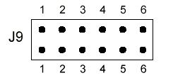
Figure 2. Output Address Selection Header
Pin 1 of header J9 is closest to the left edge of the Digital Input/Output Expansion Board. The output address is selected according to the following table:
Table 2. Output Address Selection
Output J9 Jumpers Output J9 Jumpers Address Address 0 6, 5, 4, 3, 2, 1 1 6, 5, 4, 3, 2 2 6, 5, 4, 3, 1 3 6, 5, 4, 3 4 6, 5, 4, 2, 1 5 6, 5, 4, 2 6 6, 5, 4, 1 7 6, 5, 4 8 6, 5, 3, 2, 1 9 6, 5, 3, 2 10 6, 5, 3, 1 11 6, 5, 3 12 6, 5, 2, 1 13 6, 5, 2 14 6, 5, 1 15 6, 5 16 6, 4, 3, 2, 1 17 6, 4, 3, 2 18 6, 4, 3, 1 19 6, 4, 3 20 6, 4, 2, 1 21 6, 4, 2 22 6, 4, 1 23 6, 4 24 6, 3, 2, 1 25 6, 3, 2 26 6, 3, 1 27 6, 3 28 6, 2, 1 29 6, 2 30 6, 1 31 6 32 5, 4, 3, 2, 1 33 5, 4, 3, 2 34 5, 4, 3, 1 35 5, 4, 3 36 5, 4, 2, 1 37 5, 4, 2 38 5, 4, 1 39 5, 4 40 5, 3, 2, 1 41 5, 3, 2 42 5, 3, 1 43 5, 3 44 5, 2, 1 45 5, 2 46 5, 1 47 5 48 4, 3, 2, 1 49 4, 3, 2 50 4, 3, 1 51 4, 3 52 4, 2, 1 53 4, 2 54 4, 1 55 4 56 3, 2, 1 57 3, 2 58 3, 1 59 3 60 2, 1 61 2 62 1 63 none |
Digital output can be expanded past the maximum limit for digital input. For Digital Input/Output Expansion Boards that expand digital output beyond the maximum digital input range, the digital inputs must be disabled by removing the shunt 4 on J8.
Digital outputs
To use digital output, the DAPL command OUTPORT is required. The output port type of the Digital Input/Output Expansion Board is zero.
The following DAPL listing outputs the 16-bit values in pipe P0 to the Digital Input/Output Expansion Board asynchronously:
   OUTPORT 0 TYPE=0
   RESET
   PIPES P0
   PDEF B
      DIGITALOUT(P0, 0)
      END
   START B
Note that the output address of the board in the previous example is set to B0 with all six shunts installed on header J9.
Synchronous Digital Output Expansion
Synchronous digital output expansion uses a special protocol which is implemented by the DAPL command DEXPAND. For each word of output, the data and address are encoded into four words that are sent to the digital output port. If DEXPAND is used, all digital outputs are synchronous on all Digital Input/Output Expansion Boards. See the description of DEXPAND in the DAPL manual for more information.
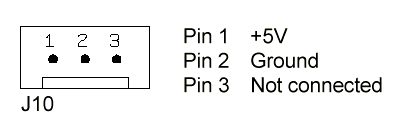
External Power Option
The Digital Input/Output Expansion Board typically requires 0.46A at +5 Volts DC. The Data Acquisition Processor can typically supply 1.5A to 2.0A at +5 Volts. The total power consumption of all expansion boards must not exceed the power availability of the Data Acquisition Processor. Please refer to the hardware documentation of the Data Acquisition Processor for more specific power availability information. If the total power consumption exceeds the power availability of the Data Acquisition Processor, then the external power model of the Digital Input/Output Expansion Board must be used.
The external power model of the Digital Input/Output Expansion Board allows an external +5 Volts power supply to be connected through connector J10. Connector J10 is a single row header on .156-inch centers. J10 is Molex part number 26-60-4030, which mates with Molex part number 09-50-3031.
External Enclosure Option
The Digital Input/Output Expansion Board is available with a single-board external enclosure option. The external enclosure provides shielding and is compatible with the European Community directive 89/336/EEC.
The single-board external enclosure has several possible end panels that allow for different external connection options for the Digital Input/Output Expansion Board. Contact Microstar Laboratories for more information on available end panels.
Backplane Connector Option
A Digital Input/Output Expansion Board is available with a backplane connector installed in J1 instead of a cable connector. This allows the Digital Input/Output Expansion Board to be used with a Digital Backplane. Connector J1 of the Digital Input/Output Expansion Board Backplane Board plugs directly into an empty slot on the Digital Backplane. See the Digital Backplane manual for more information on how to install backplane boards into a Digital Backplane and how to connect the Digital Backplane to the Data Acquisition Processor.
View other Technical Notes.