2-DAP Configuration for Measuring Control Loop Latency
Introduction

(View more Data Acquisition articles or download this article in PDF format.)
This note describes how to use a Data Acquisition Processor (DAP) board to measure control loop signal propagation delays. This is not something that everybody will want to do, but it is something that anybody could do, if necessary, to obtain a realistic determination of control loop performance.
A real-time system has two important, but very different properties: its throughput and its latency.
- throughput
- At what rate can the computing grind through data? Processing might occur at amazing rates, but, like Aesop's fabled hare racing a tortoise, you can't be sure about when the results will be ready.
- latency
- How quickly are results delivered? You might have little time to do much besides move numbers, but at least you can be sure those numbers are available when needed.
Related |
|---|
|
|
For purposes of control systems, the key property is latency: the ability to deliver a timely and regular response so that the feedback loop does not become noisy or unstable.
When a control loop is implemented using a Data Acquisition Processor, and the performance measurements are independently captured and analyzed using another DAP, this leads to a 2-DAP test configuration.
DAP boards are multitasking devices, and it is tempting to let the same DAP operate the control loop and also measure itself. Such measurements are possible to a limited extent, but there are some significant difficulties. The monitoring activities compete with the control activities for processing resources, and this can alter the performance measurements significantly. The monitoring and control updates are time-correlated, not independent, so there is a significant chance that the monitor will consistently miss worst cases, or consistently exaggerate them.
The following is a diagram of the basic 2-DAP hardware configuration for latency measurement.
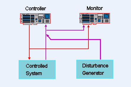
The measurement strategy is based on three key ideas:
- The controller device supports only the control updates and the data movement operations that would be done in the finished application.
- A localized disturbance is injected into the tested loop's feedback path. The resulting responses are detected when they propagate to the control output.
- All measurements are on the same time reference. The multitasking sequence of a DAP is unpredictable, but measured signals are always based on a regular sampling clock.
The System Under Test
The Data Acquisition Processor board serving as a controller will perform control and data conversion tasks in the same way as it would in the actual application. As long as the operation is stable and within a normal operating range, control output levels don't matter. A typical configuration for a DAP board under test will define
- input processing to establish the clocking rate for loop update actions,
- data pipe declarations for connections between devices and control processing, and
- task definitions for control and data conversion processes.
  // Configuration for a single-channel PID controller
  reset
  pipe      setpipe  word
  pipe      gains    float
  constant  lolim    word = 10000
  constant  hilim    word = 20000
  constant  Tsamp    float = 0.01

  //             K      Ti      Td        Z
  fill  gains    5.0    6.0     0.01      1.0
  fill  setpipe      13500

  // Delivery of control output signals
  pipe  pDrive   word

  // Receiving feedback input, sampling time
  idefine  pidsamp
    channels  1
    set IP0   s0
    time      100
  end

  // Delivering the control response
  pdefine  controller
    PID (setpipe, IP0, gains, Tsamp, pDrive, lolim, hilim )
    DACOUT(pDrive,0)
  end

  start
Data arrive at precise intervals, timed by the controller DAP's sampling clock. Responses computed by the controller algorithm are delivered with minimal delay, and without waiting for a clock.
The Testing DAP
A typical configuration for the DAP that coordinates the testing will define
- capturing the disturbance signal and the controller drive signal, based on a common hardware clock, at an elevated sampling rate for good time resolution,
- software triggering on the disturbance signal to establish the times when injected disturbances occur,
- comparable software triggering on the control drive signal to detect responses to disturbances,
- recording of the time delay between events and responses for later analysis.
  reset

  // Detection levels on disturbance and control response
  variable  DIST_LOW    word =  2000
  variable  DIST_HIGH   word =  32700
  variable  RESP_LOW    word =  3500
  variable  RESP_HIGH   word =  32700

  // Clocked sampling of disturbance and response signals
  constant    SAMPLING word = 25
  idefine  monitoring
    channels  2
    set ip0   s0     // Controller drive signal
    set ip1   s1     // Disturbance signal
    time      SAMPLING
  end

  // Detection of disturbances and disturbance responses
  trigger   tDisturb  mode=normal holdoff=100 startup=5000
  trigger   tRespond  mode=normal holdoff=100 startup=5000
  pipes     ptDisturb long, ptRespond long
  pipe      pDelay float

  // Processing to measure response delays
  pdefine  observe
    dlimit(ip1,inside,DIST_LOW,DIST_HIGH,tDisturb)
    tstamp(tDisturb, ptDisturb )
    dlimit(ip0,inside,RESP_LOW,RESP_HIGH,tReceiving)
    tstamp(tRespond, ptRespond )
    $Binout = (ptRespond - ptDisturb)*SAMPLING*2
  end

  start
Disturbance Signals
A typical disturbance signal is a small square wave, added to the ordinary feedback response. The sharp rising edge of this disturbance usually results in a sharp controller response that is easy to detect. Then the steady flat tops of the disturbance waveform allow for settling time between the sharp edges.
Timing of disturbance signals is not critical. Precise periodic waveforms are not required.
The example configuration assumes that the controller operates in a stable manner in combination with a real system, or something that responds sufficiently like one. You will get no useful measurements if the control loop is unstable and oscillating hard, or clamped against an output limit.
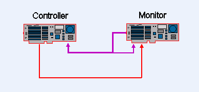
Offline Testing
The point of the control latency measurement is to determine controller delays, not identify system closed loop dynamics. The dynamics of an actual system can get in the way of delay measurements. Sometimes it is too awkward, too expensive, or too dangerous to perform measurements on an actual system. The actual system really doesn't matter for the purposes of testing controller delays. You just need the loop to stabilize.
If you are able to set up a simple "R-C lag filter" as a substitute for your actual system, and you can get the closed control loop to stabilize with this, it is an excellent configuration. It is inexpensive and has a natural filtering response that will control measurement noise. The disturbance signal can be coupled into the RC network to produce crisp edges that are easy to detect in the controller output.
As an alternative to building an electronic network, it is often possible to let the testing DAP simulate an adequate system response. The disturbance can be computed as well, eliminating the need for any supplemental electronic devices.
The following modifications to the testing DAP configuration will compute a small square wave disturbance, a first order lag response for simulation, and a combination yielding the feedback signal.
  // Declare additional elements for simulation
  constant  cTlag   float  = 500
  pipes     prsim1 word, prsim2 float, pdisturb word
  fill      prsim2    0

  // Declare properties of disturbance waveform
  constant  wavelength word   = 10000
  constant  amplitude  word   = 800

  // Simulate first-order lag response with disturbance
  pdefine  simulate
    squarewave(amplitude,wavelength,pdisturb)
    prsim2 = (prsim2*cTlag + ip0)/(cTlag+1)
    prsim1 = prsim2 + pdisturb
    dacout(prsim1,0)
  end
Testing Multiple Loop Configurations
Data Acquisition Processors gain tremendous advantage from processing data in blocks. The bulk of the computational cost is usually related to operating the hardware and moving the data through the pipe system. For a DAP system, the cost for fetching a block of data is not much more than the cost of fetching just one value. If the sampling rate is boosted by a factor of N, a set of N control loops can share input operations, each channel receiving data at the original rate. Each loop will have similar control processing, but each can have its own independent states and tuning. In all respects other than shared timing of input and output activity, the loops operate independently.
You can use a 2-DAP configuration to measure latency of multiple-loop controllers with just a few variations in the test configuration. Do these things for the duration of the test.
- Take input data for all channels from a single physical line, rather than the usual independent physical lines.
- Monitor the output of only one loop. All loops will be subject to the same sorts of delays, so measuring any one of them is sufficient.
- Route the same feedback signal to all of the controller feedback channels.
- Configure all loops to regulate the same levels.
Analyzing Test Results
There are three main sources of delay in measured time delay results.
- Sampling. Events can happen at any time. Controller devices can only respond after they see an event. If an event happens to occur just after a sample is captured, that event won't be observed until the next sampling instant. If there is no correlation between events and the sampling clock, the events could occur at any time between sampling instants, so the average delay due to sampling is 1/2 of the sampling interval for each channel, and, in the the worst case, equals the sampling interval on the channel.
- Buffering. Data taken from a converter device must be moved into memory somewhere for tasks to access. You want data to remain in buffers for as short a time as possible, to keep latency low.
- Processing delays. Processing tasks must compute the control drive outputs. If processing is temporarily dedicated to moving data out of a converter device, or managing task context, or allocating a memory buffer, there is a delay. One or more of these delays could occur at any time. They are bounded but unpredictable. They must be much smaller than the sampling interval on the average, or the processing would not be able to maintain the pace of the sampling.
Because of the variation in the delays, you will need to take many measurements and analyze the results statistically, looking at the typical and worst cases. Some guidelines for analyzing the test results:
- If the expected value of response delay is well under 1.5 times the time interval to scan the channel list, you do not have excessive buffering or processing delays and will not experience consistently delayed updates.
- If the worst case delay is less than 2 times the time to scan all input channels, you might still have jitter, but you will never have an "overlapped and missing" late update.
- If the worst case delay is larger but infrequent, you will experience intermittent late updates. Depending on your system response dynamics, occasional late updates could be of no consequence.
Return to the Data Acquisition articles page.