Thermistor Application
|
|
|
|
|
|
|
Precise Measurement Using a Thermistor


This page describes an application using an individually-calibrated thermistor to obtain highly accurate measurements of ambient temperature. This is an important side-problem for the HTST pasteurization application on this site: specifically, the temperature measurement of the thermocouple sensor used by that system does not completely determine the process temperature. The cold junction temperature must be measured accurately as well. Many of the application configuration issues are predetermined to satisfy the requirements of that system. Better than 0.1 degree C accuracy is required for the cold junction measurement in order to meet the stringent total measurement error requirements.
A sensor is needed that can measure absolute temperature with good stability and accuracy. Within the thermally protected environment where the thermocouple is terminated:
- Temperatures changes are small.
- Temperatures changes occur very slowly.
- The measuring device is subjected to minimal operating stress.
This is a perfect place to take advantage of a thermistor's excellent responsiveness and accuracy.
Hardware details
The pasteurization application uses an MSXB 065 signal conditioning and filtering board. The application reserves one of the channels on this board for cold junction measurements.
The boards in the Channel Architecture conform to Eurocard formats, so you can easily obtain boards that fit within the enclosure and can meet EMC emissions standards.
The MSXB065 and the thermocouple termination boards reside in an MSIE001 half-size standard rack enclosure. One slot is used by the interface board connecting the Data Acquisition Processor (DAP) board to the analog backplane. One slot is used by the MSXB 065. There is at least one slot for a thermal barrier, and then a slot used by a custom thermocouple termination board. The custom termination board provides a thermally stable environment, where the temperature can be measured accurately at the thermocouple cold junction terminals.
A cable must be built to connect the MSXB 065 to the thermocouple termination board.
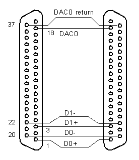
Figure 1 - cable between boards
The thermocouple termination board is basically just a set of connectors. On the outside of the end panel, there are two connectors: a 37-pin D connector attaches to the signal conditioning board, and a thermocouple connector attaches to the thermocouple wires and their shield. On the inside, the board is blank and supports a terminal strip.
It is important for the thermistor to be mounted physically as close to the thermocouple wire termination as possible to avoid a temperature offset. One way to do this is to physically bond the thermistor body to the connector on the inside of the panel. Route the thermistor leads to connect at the terminal strip.
Beyond the point where the thermocouple wires terminate, use well-balanced conductors to connect to the terminal strip. On the other side of the terminal strip, connect to the excitation source and the differential measurement pins from the signal conditioning connector. The following diagram summarizes the electrical connections.
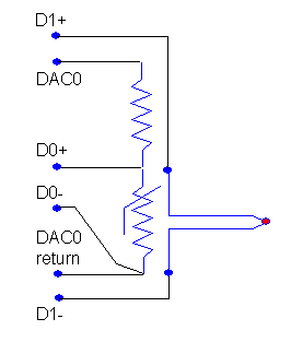
Figure 3 - thermistor connections on termination board
Thermistor characteristic calibration
The MSXB065 board is configured for gains of 25 to detect
very small thermocouple potentials. After applying the gain, the
results must remain under +5 volts to be within the range of the
Data Acquisition Processor. That means, 5/25 = 0.2
volts is a reasonable upper bound on the voltage across the
thermistor when its resistance is maximum.
We pick a thermistor with a nominal value of about 1K at 25 degrees C. It happens to have a maximum value of about 2K in the operating range. To stay below 0.2 volts when the excitation voltage is +5 volts, we need a load resistor of about 50K. Choose standard value 56K for the loading resistor. Using a precision ohmmeter, determine the actual value. We will assume a measured value of 56.18K.
Assume an ambient temperature range 10 to 40 degrees C. The operating environment is unlikely to vary by this much, because milk must be refrigerated most of the time, and regulating the ambient temperature helps regulate the storage temperature. Even though this is a restricted range, the thermistor characteristic is nonlinear over this range and we need a correspondingly nonlinear characteristic to evaluate its response. See the thermistor calibration page for more information about how to do a simple three-point calibration. Here is the calibration data set. We will use the first, center, and last terms for an exact fit and evaluate the approximations at the other two points to check the interpolation accuracy.
|
Temperature (degrees C) |
Observed voltage (gain 25X) |
Resistance (Ohms) |
|---|---|---|
| 10 | 4.274 | 1989 |
| 18 | 2.974 | 1369 |
| 25 | 2.190 | 1002 |
| 32 | 1.625 | 740 |
| 40 | 1.175 | 533 |
   Steinhart-Hart Equation Three-Point Fit
a = 1.6901e-3    b = 2.3284e-4    c = 1.6663e-7
Verifying at midpoints:
for R = 1369  -->  T = 18.01  (compare: 18.00)
for R = 740   -->  T = 32.05  (compare: 32.00)
The model is able to fit the data to better than 0.1 degree, which makes it possible to keep the total measurement error within 0.5 degrees.
Excitation for the thermistor
Thermistors are not self-powering. An excitation is required to force a current through it, and the resulting voltage tells us the resistance value.
The MSXB 065 does not have a reference voltage source in the ordinary sense. It does, however, have an alternative that is almost as good. When jumpers are installed at position J8 (this is the default configuration) the outputs of the DAC (digital-to-analog converter) devices on the DAP are routed through the MSXB 065 to pins on its 37-pin "input connector." (This makes the term "input connector" a little awkward when these signals are outputs!) We only need one of these signals to use for the excitation. There are a few minor hazards.
- When you use a DAC device as a voltage source in this way, without any means to latch and hold the signal level at the receiving end, the DAC output must remain undisturbed. For example, if you use a
DACOUTprocessing command that reads its value from a variable, the value of that variable must never be changed. - There is limited drive current. With loading of over 50K ohms driven by a voltage of +5 volts or less, there is about 0.1 mA, well below this limit.
- Special configuration is required to set up the DAC to operate this way.
Excitation source configuration
A digitizer count of 32768 corresponds to the full input range of +5.0 volts (so numerically reachable output levels are one tick short of this). Suppose we pick a 4.0 volt excitation, below the maximum range, to drive the loaded thermistor. Then the following calculates the desired digitized excitation level.
(4.0 / 5.0) x 32768 = 26214 counts
In the DAPL configuration, declare a source pipe to deliver this value to the DAC. Insert the data into that pipe.
PIPE  EXCITATION WORD
FILL  EXCITATION   26214
In the processing section, define a task that moves this value to the selected output DAC.
DACOUT( EXCITATION, 0 )
When this task begins to execute, it will move the specified
output level to DAC0. After this, the DACOUT task
will be starved for new data and unable to change the output DAC
further. The DACOUT task goes to sleep permanently,
and does not get in the way of other processing.
While the converter electronics are very precise, you cannot
be sure that small offsets or losses aren't affecting the
voltage actually appearing across the thermistor and loading
resistance network. You can improve accuracy by measuring the
actual voltage with an accurate high-impedance voltmeter. If
necessary, adjust the value loaded into the EXCITATION
pipe, upward or downward (each level change of 16
adjusts the 12-bit converter output by one "quantum" on the
DAP5200a). Adjust until the measured value is as close to a
perfect 4.000 volts as possible.
Filtering on the CJC channel
Filtering is not strictly necessary for measuring the thermistor voltage on the CJC channel. With the high sensitivity of the thermistor and the highly protected environment, it experiences little noise disturbance. However, it remains true that any signal component above 500 Hz cannot possibly be useful cold junction temperature information. Hardware filtering is used for the noisy thermocouple measurements, and there is no harm in filtering the less-noisy thermistor measurements the same way.
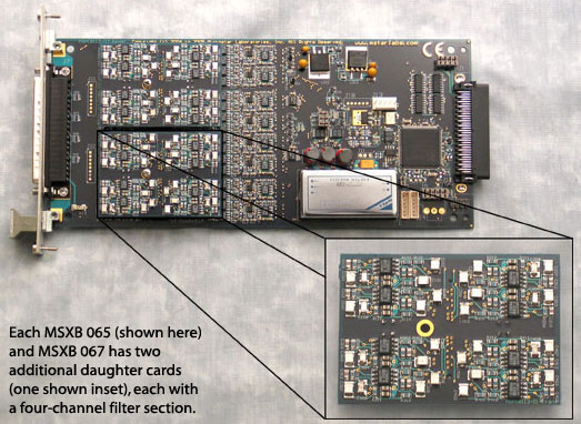
Figure 3 - Filtering channels on a MSXB065 board
This application only uses one thermocouple channel, but it could be expanded to measure additional channels. As long as all cold junctions are maintained at the same temperature, you only need one cold junction measurement.
Configuring the measurements
In the HTST pasteurization
application, the input channel IP1
is used for measuring the thermocouple, while channel
IP0 is reserved for measuring the CJC
thermistor. No additional gain is required for the CJC
measurement, so its gain level is set to 1 for acquisition.
Its samples alternate with the samples of the thermocouple.
For 1500 samples per second on each channel, the time
interval between sampling events is 333.33 microseconds.
SET  IP0  D0    1     // CJC thermistor
SET  IP1  D1    40    // thermocouple
TIME   333.3
You can export the configurations you develop with DAPstudio software, and run them on your DAP independent of DAPstudio or other GUI packages.
The DAP 5000a processing capacity is useful for independently processing the CJC temperature readings in parallel with the thermocouple readings. Changes in the cold junction temperature will be very slow, so simple averaging that reduces each set of 10 thermistor measurements to one averaged measurement will do the trick. Multi-tasking is automatic in the DAPL system.
// Noise and rate reduction by filtering
AVERAGE(IP0, 10, PAMBIENT)     // cold junction
FIRLOWPASS(IP1, 10, PREDUCED)  // thermocouple
Converting measured voltage to resistance
First, you need to know the thermistor resistance. To determine this, you need to convert the measured voltage from scaled converter ticks into physical voltage units. The range limit 32768 corresponds to 5.0 volts. The gain of 25 applied by MSXB065 board amplifiers must also be compensated. The following conversion can be used.
VTHERM = PAMBIENT * (5.0 / 32768) / 25
Now, use the following voltage divider formula to
combine the measured voltage VTHERM, the known 4.0
volt excitation level, and the known loading resistance 56.18K,
yielding the value of the thermistor resistance in ohms,
to high accuracy.
RTHERM = 56180.0 * VTHERM / (4.0 - VTHERM)
Converting resistance to temperature
Each time a thermistor measurement value is received, it is converted to the equivalent temperature using the calibrated response curve. Probably the easiest way to do this is the THERMISTOR command, available on this site. Make sure that the SENSORM module is installed on your system. The conversion coefficients are specified in a DAPL vector.
   VECTOR  CALIB0  FLOAT = \
     (0,    1.6901e-3, 2.3284e-4, 1.6663e-7)
Another useful way to apply device-specific calibrations is the DAPL system's SCALE command.
Later, in the processing section, specify this device model as you convert the measurements into temperatures.
THERMISTOR(RTHERM, CALIB0, PCOLDJUNC)
To complete the processing, combine the cold junction temperature result with the temperature difference result from the thermocouple.
TADJUSTED =    ... // apply thermocouple calibration
TEMPERATURE = TADJUSTED + PCOLDJUNC
Now you can route the stream of TEMPERATURE
measurements to any location you wish, test the range
and signal alarms in real time, collect statistics for
data logging, etc.