Configure Groups of Channels with DAPlog
Clicking, holding, and dragging the cursor over multiple cells of the channel selection grid can activate useful groupings of channels. Here are some examples.
Selecting Consecutive Input Channels
Selecting horizontal rows of channels selects a group of consecutive logical channels to configure. The following sequence will select single-ended input pipe channels S2 through S9 and assign them to the logical channel pipes IP0 through IP7.
- Under the
Input Pipestab, move the mouse cursor to theInput Pipe Edit Selectiongrid, and press the right mouse button to bring up a pop-up menu. SelectClear All. - Click the
0button and drag the mouse to select all items through to the7button. - Type "
S2" in theInput Pinedit box. - Move the mouse cursor over the
Input Pipe Edit
Selection
grid, press the right mouse button to bring up a pop-up menu, and selectSelected Channels|Input Pin Same As First.
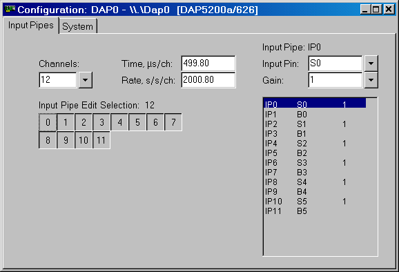
Alternating Analog and Digital Port Samples
Channels that are de-selected do not use a previous configuration. You can use the following sequence to configure alternating samples of single-ended analog channels and digital port samples.
- Under the
Input Pipestab, move the mouse cursor to theInput Pipe Edit Selectiongrid, and press the right mouse button to bring up a pop-up menu. SelectClear All. - Click the
0button and drag the mouse down to select all items in the column. - Repeat with the
2, 4,and6buttons. You will obtain a vertically-striped display. - Type "
S0" in theInput Pinedit box. - Move the mouse cursor over the selected channels display
at the right. Click the right mouse
button to bring up a pop-up menu, and select
Selected
Channels | Input Pin Increment From First
. This assigns analog channels in sequence. - Click the
0button and drag the mouse down over every cell in the channel selection grid. This will invert all selections. - Drop down the selection menu on the right of the
Input Pinedit box and select pin type B, keeping the default B0. - Right click on the selected channel display at the right.
Press the right mouse button to bring up a pop-up menu, and select
Selected
Channels | Input Pin Increment From First
. This selects the digital ports in sequence. - Right click the mouse on the
Input Pipe Edit Selectiongrid, and chooseSelect Allfrom the dialog.

Mixed High and Low Speed Sampling
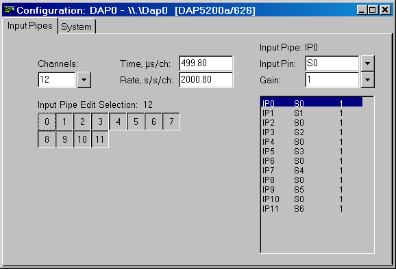
The DAPL system does not limit you to sampling a given hardware channel only once. A special hardware signal where events should be detected quickly can be sampled frequently, while other signals are sampled in the normal sequence.
- Select all of the channels in the channel selection grid.
- In the display on the right, select logical channel IP0 and configure it to sample pin S0.
- Right click on the display, and from the dialog select
All Channels, and thenInput Pin Same As First. - Repeat the methods for selecting
alternate columns, so that channels
S1,S3and so forth are selected. - In the display at the right, click on channel IP1 to select it.
- Configure it to sample signal pin S1.
- Move the cursor over the display window and click the right mouse
button to bring up a pop-up menu, and select
Selected Channels | Input Pin Increment From First. This assigns analog channels in sequence. - Right click the mouse on the
Input Pipe Edit Selectiongrid, and chooseSelect Allfrom the dialog.

Return to the DAPlog examples page.