Timing for Rotating Equipment
|
|
|
|
|
|
|
Rotational Plus Absolute Timing With Digital Counter Boards

(View more Data Acquisition articles. Or view an example counter-timer system configuration.)
Most measurements of rotating machines are captured at a set of equal angular increments that span each rotation. To determine angular position, the usual practice is to mount an optical encoder device on the shaft. Optical encoders provide one "top dead center" (TDC) output pulse per rotation, plus a separate stream of pulses at equal angular intervals. The TDC pulse indicates the start of each rotation. For example, engines time their fuel injection and firing cycles based on an angular displacement from the TDC position.
Instead of sampling at equal time intervals based on a precision oscillator, your DAP (Data Acquisition Processor) board can use the encoder pulses to initiate sampling action. Depending on the rotation speed, the time between samples might vary, but the sampling locations are always the same.
Related |
|---|
Digital counters such as the 10 counters on an MSXB 036 counter/timer board are rather simple devices that just count pulses. They have no concept of direction, so an "up pulse" and a "down pulse" would be recorded the same way. Most motors or engines rotate in one direction only, so this restriction usually is not a problem. (Otherwise, you probably want to use a quadrature encoder device and an MSXB 050 Quadrature Decoder Board.)
The advantage of a separate board for counting is that it is completely independent of any other timing constraints or sampling activities. It can count irregular events, run on a separate clock at an unrelated rate, or operate much faster than sampling conversions could go. These are interesting features, but it is not always clear why you might want to use them.
Mixed Rotation and Absolute Time Analysis
Sometimes knowing the angular positions of every measurement is not completely sufficient. For example, you couldn't tell from your data set whether your engine was rotating at 60 RPM or 6000 RPM. And that makes a big difference!
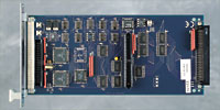
That is where the MSXB 036 Timer Counter board comes in. It has
an embedded 5 MHz timing clock. Counting these pulses is equivalent
to measuring elapsed time. To use this oscillator, add the ICLOCK option (Internal Clock) when you define the input channel that reads the selected timer.
For example:
SET IPIPE2 CT2 ICLOCK
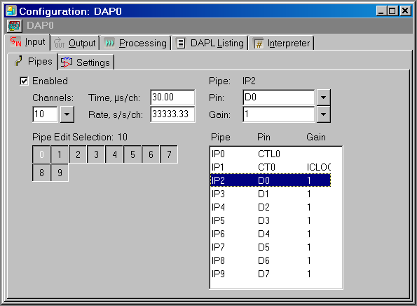
Using DAPstudio software to configure the MSXB 036, you must override the "gain field" on the Clock Timer channel type, as shown in the following screen capture.
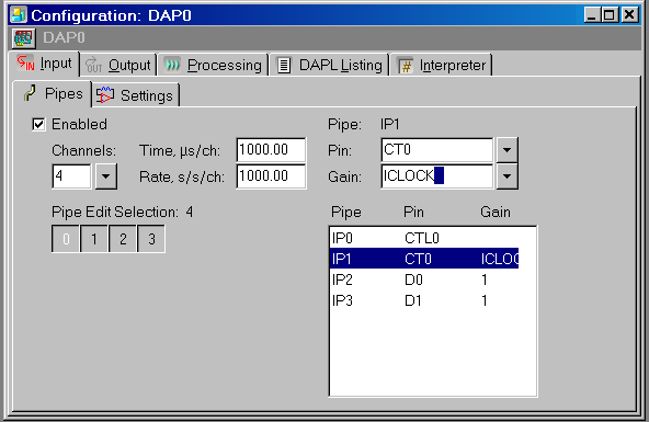
When configured to count pulses from the embedded 5 MHz clock, the Counter/Timer board will ignore its external digital input pin. By reading the value of the running count as you capture measurement samples under encoder control, you can determine the elapsed times between measured samples, or equivalently, the rotation speed.
Using MSXB 036 Boards
Related |
|---|
|
|
Counted events could occur at any time. If a sampling event caused reading of the count register at exactly the same instant that the register is being updated, several bits could be in an uncertain state because of carry propagation. This could produce disastrously bad readings. To guarantee that this problem never happens, you must operate the board on two cycles, a latch cycle and a read cycle. During a latch cycle, the current contents of the counter are copied to an output holding register in a manner that is guaranteed safe. During a read cycle, you retrieve a copy of the latched count from the register.
If you use encoder pulses in the ordinary way, there seems to be a severe problem at this point. The first encoder pulse latches the counter, but produces no useful measurement. The next encoder pulse reads the elapsed time count. In the meantime, the machine is still turning, and two encoder pulses were consumed with no machine measurements captured. The problem only gets worse if you have eight cylinders to measure.
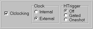
What you really want is that the encoder indicates where measurements should start, and then the measurement process spins through all of your data channels quickly, capturing the elapsed time count and one full set of measurements as quickly as possible, finishing this before the next encoder pulse arrives. You can do this by using the Data Acquisition Processor channel list clocking feature. Your encoder starts the sampling, and the DAP provides the additional clocking to spin through the list of channels.
Channel list clocking is enabled by default. You can verify
that it is enabled in DAPstudio by clicking on the Input |
Settings tab.
You must configure the measurement channels and their timing. When using an MSXB 036 board, you can spin through the list as quickly as 3 microseconds per channel. For example, suppose that you are measuring the pressure in 8 engine cylinders. Including the two clock/timer channels, there are 10 channels total. So you can specify a total cycle time of 30 microseconds (3 microsecond intervals between channel measurements) as shown in the following screen capture.
As a check, you can click the DAPL Listing
tab and verify that the interval on the time
configuration command is 3.00 or larger. The speed limitation
could be somewhat constraining, but it is sufficient to
capture 16 measurement channels in 128 positions at 8000
RPM. This should be good enough for most applications.
Processing Options
Related |
|---|
|
|
The "timestamps" that you get back from the counter board have a
limited range. The 16-bit counters continue running and growing,
even as you read the current values. Eventually, the counters will
reach an upper range limit and wrap back to start again
at 0. You can observe the jump from a large value to a smaller one,
thus determining that a wrap event occurred, but it is easier to
let the DAPL system correct for this automatically, using the
CTCOUNT or CTRATE processing command.
CTCOUNT- Unwraps the values obtained by the count register, reporting the total count as a 32-bit accumulation.
CTRATE- Reports the number of new counts obtained since the last reading, accounting for the wrapping in the counter register automatically.
For example, the following processing task removes the wrapping
anomalies and places the cleaned-up time interval values
into the pipe PTSTRIP.
CTRATE(IP1,PTSTRIP)
Conclusion
When you need to measure rotating machinery, you will usually need to measure at consistent rotation angles as determined by an encoder. When you do so, you don't have to lose all elapsed time information in the process. Using the MSXB 036 Counter/Timer Board with your Data Acquisition Processor hardware, you can have three independent clocking processes working for you simultaneously:
- your encoder pulses to initiate sampling
- a very high-rate elapsed time counter
- a high rate sampling interval timer
You can then measure multiple channels, and relate samples in your encoder-dependent measurement sequence to the rotation speed or the elapsed time at which the samples were captured.
This gives you data sets uniformly spaced in angle but tagged with elapsed time information. You do not get an equivalent data set, uniformly spaced in time covering the same span of rotation. That kind of processing is called "order analysis." It is certainly possible, but it must be a separate topic.
Return to the Data Acquisition articles page.