Calibrating RTD Sensors
|
|
|
|
|
|
|
Calibrate RTDs
RTD devices depend on the fact that metals increase resistivity approximately in proportion to temperature. Their thermal characteristics are conventionally described by a base resistance value and a conversion characteristic that equals 1.0 exactly at 0 degrees C.
R = R0 ( 1.0 + ka * T + kb * T2 + ... )
At T = 0 degrees C, the measured value of R equals the base
resistance value R0. Immersing the RTD
sensor in an ice water bath is a way of measuring this parameter
directly. RTDs are manufactured with relatively tight
tolerances, and many applications can assume that the nominal
device parametes are sufficiently accurate.
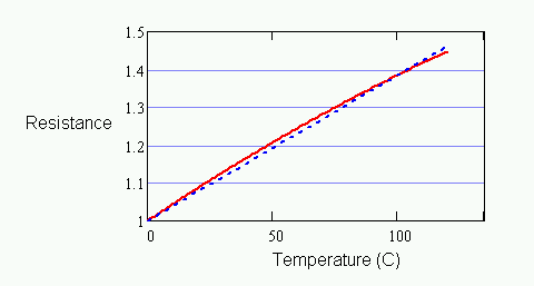
Though inexpensive materials can be used for making RTDs, platinum RTDs have a response that is close to perfectly linear. A common approximation is to draw a "straight line curve," starting from the nominal normalized resistance 1.0 at temperature 0 degrees C, extending to the normalized resistance for the device at 100 degrees C.

Figure 1 - RTD characteristic and alpha approximation
The illustration above exaggerates the curvature so that there is something to see. For platinum RTD devices, the slope of the constructed line — the alpha parameter value — is 0.00385 per-unit resistance change per degree C. The difference between this straight-line approximation and the exact curve is about 0.4 degrees, with the maximum error occurring at roughly 50 degrees C. If this is already within an acceptable tolerance, there is no point in doing any additional calibration. This is what makes RTDs so popular.
For accurately modelling RTD response through its full temperature range of a few hundred degrees, a higher order polynomial is used. For platinum materials, a polynomial of order two is usually sufficient for full measurement accuracy. For less expensive but less linear RTD devices, you might need a polynomial order as high as six.
Unfortunately, a conventional RTD characteristic maps temperature to normalized resistance. This is usually the reverse of how you want to use it — to map the normalized resistance into a temperature. Inverting the curve equation is no problem for a first or second order polynomial, but for higher-order polynomials you must either use iterative methods or abandon the standard form.
The steps to determine the temperature of an RTD, using a calibrated characteristic curve in conventional form, are as follows:
- Measure operating resistance in ohms.
- Divide by the normalizing resistance factor.
- Solve the RTD equation in the inverse direction to determine the temperature corresponding to the normalized resistance.
Usually it is most efficient to compute RTD characteristic
curves directly. As with any sensor, it is possible to
select corner points at intervals along the
characteristic curve and represent the inverse curve
with a piece-wise linear approximation, and evaluate it
using the INTERP command. Intervals of about 50 degrees C should work well.
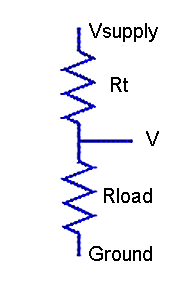
Operating over a wide temperature range, you will probably do well to measure the RTD resistance using a simple voltage divider network and unity amplifier gain.

Figure 2 - RTD in voltage divider network
Operating over a limited temperature range, you might want to consider a bridge configuration. If the bridge is reasonably well balanced, you can measure the differential voltage across the bridge with a gain amplifier to improve measurement resolution. A linear mapping from differential voltage to temperature will then yield an accurate conversion.

Figure 3 - RTD in bridge network
You can use the DIVIDER command or the
BRIDGE command for deriving RTD resistance from voltage
measurements. Both commands are available on this site. You can
use the RTD command, also available on this site,
for the inverse calculation of RTD temperature from normalized
resistance. The RTD command also provides extensions, not
discussed here, for multiple-part curves covering sub-zero temperatures.


