RTD Application
|
|
|
|
|
|
|
RTD Measurements for Roaster Control
Producing a rich, aromatic cup of java requires a blend of art, science, and good coffee beans. A critical step is the roasting of the beans. There are hundreds of complex organic chemicals that produce the flavors and aromas. Roasting brings out some of these, and produces others, in a manner highly dependent on timing and temperatures. Good roasting techniques can produce quite acceptable results from relatively low-grade beans; bad roasting can produce quite dreadful results from the best high-grade beans.
Profile roasting
Green coffee beans are placed into a drum or chamber, where they are agitated or tumbled as they are roasted by hot air. There are four controllable variables:
- temperature of the hot air
- air flow rate
- temperature of the beans
- stir rate
The most successful and repeatable control strategy is called profile control. Rather than trying to hold specific temperatures, the temperature targets are treated as a continuously changing trajectory. The amount of heating at "each level" depends on the rates of temperature change.
Temperature sensing
The critical variable is the temperature of the beans. Other variables can help to improve the control of the critical variable. The heated air is easier to measure, but it can differ from the bean temperature by as much as 200 degrees F, so it is not a sufficient indicator by itself.
A thermal probe measuring the temperature within the coffee beans provides the most important feedback. The probe must withstand the pounding as beans are tumbled. Because of its rugged sheath, this kind of probe will not respond quickly, but the temperature profile will not change very fast either, and a reasonable balance is maintained.
Either a thermocouple or RTD probe could work for this application. We will select an RTD probe because it is reliable, accurate, stable, easy to use, and well suited for an operating temperature range of 100 to 500 degrees F.
RTD electrical connections
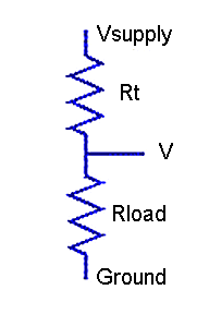
RTDs are often driven by specialized, regulated current source devices, but most of the time all you really need is an accurately-regulated voltage source and accurately-measured load resistor. Connect them in a voltage divider configuration.

Figure 1 - RTD in simple divider network
The voltage across the RTD changes roughly in proportion to the resistance change of the RTD, which changes roughly in proportion to changes in temperature. The nonlinearities are simple and can be computed exactly, to yield accurate measurements.
Selecting a platinum RTD probe with a 500-ohm nominal resistance (PT500 characteristic), its alpha approximation (usually given as 0.00385 per-unit per degree C) tells us that the resistance changes from about 570 ohms at 100 degrees F, to 1000 ohms at 500 degrees F. If we select a series load resistance of 12K and excite the network with a +5.0 volt source, the voltage across the RTD will vary from about 0.2 to 0.4 volts. Amplify by a factor of 10 to get the range 2.0 to 4.0 volts, for excellent measurement resolution.
Accuracy of the measurement will be affected by tolerances in the resistance values:
- The load resistor value can vary from nominal.
Measure the actual resistance value with an accurate ohmmeter. - The RTD base resistance can vary from nominal.
Measure the actual RTD resistance and its temperature as accurately as you can. Then calculate the RTD base resistance at the reference temperature using the standard device curve. For a standard Pt500 device:Tf = measured temperature in degrees F Rmeas = measured RTD resistance in ohms Tc = (Tf - 32) * 5/9 Rbase = Rmeas / (1.0 + 0.003908 * Tc - 5.775e-7 * Tc2)
A DAP board's voltage reference can supply the 1/2 milliampere of current required to power the resistive network, while holding the reference level of +5.0 volts closely. If properly calibrated, the DAP will have negligible offset and gain errors.
Processing the measurements
The following shows how the calibration and conversion data are applied in the DAPL system.
CONSTANT  RTDbase   float = 500.2
CONSTANT  LOADohms  float = 12088
CONSTANT  Vexcite   float = 5.0
VECTOR TypePtRTD float = ( 0.0,0.003908,-5.775E-7,0,0,0,0 )
The input declaration sets the amplifier gain to 10 for measuring the RTD voltage (and some other temperature measurements). The measurement rate is established by setting the time interval in microseconds between sampling events. The rate of data arrival can be used as a timing base for driving all automatic processing.
IDEFINE  measurement
CHANNELS   4
SET  IP0   S0   10    // RTD voltage
SET  IP1   S1   10    // heated air
SET  IP2   S2   10    // environment
SET  IP3   S3         // humidity
...
TIME  ...
The processing includes commands that convert the captured voltage measurements into the corresponding temperature measurements. Two of these are DAPL expression tasks, and two are specialized downloadable commands available on this site.
PDEFINE  processing
// Correct for amplifier gain
RTDvolts = IP0 / 10.0
// Compute RTD resistance
DIVIDER( RTDvolts, LOADohms, Vexcite, RTDohms )
// Convert RTD resistance to equivalent temperature
RTD( RTDohms, RTDbase, TypePtRTD, TEMPRdegc )
// Convert temperature to Fahrenheit
TEMPRdegf = (9*TEMPRdegc/5)+32
// Perform control algorithms here...
// Select data for host displays here...
END
More than just measurements
Clearly, if monitoring one temperature were the complete story, a DAP system would provide more capability than you need. But an automated roasting process needs many other things to be successful. In addition to the basic measurements, DAPs can support the following:
- Supplementary measurement channels
- Regulated sources
- Trajectory generation
- Device outputs
- Interactive control algorithms
- Local process monitoring
- Remote data display and data logging
For supporting integrated measurement and control activity on multiple channels, the ability to incorporate RTD measurements along with other data capture and processing can be a real advantage. With most of the low-level details already covered, higher-level systems can concentrate on use interactions, profile configuration, and data management.


