Output Triggering Technology
|
|
|
|
|
|
|
|
|
|
|
|||||||||||||||
|
| | | | |
||||||||||||||||||
Overview of DAP Output Triggering and Clocking
Related |
|---|
|
Output triggering modes relate closely to the triggering modes for input sampling. |
DAP output triggering and clocking are supported on DAP models that have digital to analog output converter hardware. Triggering and updating modes can be used in any combination, though certain combinations are more useful. All triggering and updating modes are specified in a downloaded DAPL configuration script.
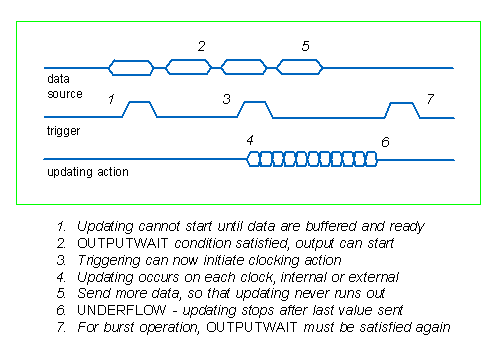
- Triggering determines when updating sequences begins, and depending on the mode, when they end.
- Updating determines the instants at which digital to analog output conversions are performed.
- Burst control determines whether there is a single output sequence, or whether updating action is reinitialized and can be restarted.
In some situations, software triggering provides an alternative with more flexibility. Typically, the software triggering provides data intermittently, and each time that it does so, the output updating provides the regular timing necessary to convert the buffered numbers into signals.
The output operating modes are very similar to the input sampling and triggering modes, but there are some fundamental differences. Though input sampling starts with empty memory and stores data, output updating uses existing data from memory. It cannot start until sufficient data are available to sustain hardware operation. It is relatively easy to generate a specific number of output updates and use an intentional underflow to stop updating when necessary.
There are three triggering modes:
- OFF. The default configuration. Updating begins as soon as possible after the output configuration is started.
- ONE-SHOT. The first active-high level on the triggering signal, after updating is loaded and ready, will initiate an output sequence.
- GATED. Updating occurs while the triggering level is active high, and is suspended when the triggering level is inactive low.
After updating starts, samples are delivered for conversion on each active-high pulse of the digital updating clock. There is an uncontrolled transient interval until output levels stabilize after a digital value is latched for conversion.
The clocking signal is selected by the CLOCKING
configuration. There are two clocking modes:
- INTERNAL. The default configuration. Updating is driven by an adjustable digital clocking signal derived from the precision on-board oscillator.
- EXTERNAL. Updating is driven by a dedicated external digital clocking line.
The two updating modes are:
- SINGLE CLOCKING (CLC off). One sample is converted and the output updated per each active high pulse in the digital clocking signal. Clock pulses are typically produced by an external time base to match a reference frequency or position encoder.
- CHANNEL LIST CLOCKING (CLC on). The default configuration. After external clocking initiates sampling, the internal clock is used for subsequent samples, until every measurement channel has a sample.